Introduction
Invention title
Background of the invention
Summary of the invention
The drawings [in column to right]
Detailed description
Introduction
In this column, there's text relating to my submission to the United States Patent and Trade Mark Office (USPTO). This New Vineyard / Orchard / Polytunnel Growing System is an invention which was awarded a Patent Pending in the United States by the United States Patent and Trade Mark Office (USPTO) in December, 2022.
In patent documents, line drawings are
used to illustrate the subject matter - they are utilitarian, not included
for any aesthetic qualities.
This isn't a patent document and in this section, I use images of various
kinds to illustrate the page. All the diagrams here, with a
very few additional diagrams
not shown here, were
included in the submission to the United States Patent and Trade Mark
Office. None of the photographs were submitted. As I explain in the
column to the left, some information is omitted here, including the detailed
keys to drawings and detailed explanations. I
include in this column introductory material to explain the working of the
New Growing System (NGS).
The material here is based on the text and drawings I sent to the Patent Agents who have acted on my behalf and the modified text written by one of their Patent Agents. It's only in the section 'Detailed description' that the two show significant differences. For the time being, I omit the 'Detailed description' section, which contains, of course, the detailed information about how the invention is constructed, how it works, how to operate it in its various functions.
I'm completely willing to supply enquirers with much fuller information, including the information in the 'Detailed description' section, as well as helpful information on the drawings not provided here. For example, I can supply the identity of components labelled in the drawings with numbers. I want to be as helpful as I can, if I think that enquirers can understand my circumstances. There's disclosure of the invention now, after filing, but in the United States, my interests are protected by a year by the status of the invention 'Patent Pending.' To protect my interests beyond that point, I have to convert the patent into a non-provisional patent by supplying new documents, which are subjected to the complex process of patent examination and the result depends upon USPTO.
In countries other than the United States, my interests aren't protected. Patent documents are intended to make it possible for a hypothetical person with skill in the particular art to construct the device or system. Even so, realistically, constructing a device or system successfully so that it works in an optimal way, often needs supplementary information. I'm in a position to supply the information but it's reasonable to expect something in return, in countries where the system isn't protected by patent law - all countries except for the United States.
The NGS includes a variety of structures for growing climbing plants such as grape vines. The support for the grape vines differs substantially from the supports of all other trellising systems. NGS structures can also be used for growing some orchard crops, such as apples, using supports very similar to the supports for growing grape vines, with similarities to the espalier system. Traditional orchards, with apple trees quite widely separated, cannot make use of NGS. The system can also be used as a polytunnel substititute, for taller crops such as tomatoes and a wide variety of low growing crops.
Invention title
Integrated dual layer structure and structure-group system with modifiable components and configurations for growing, protected cropping, protected working, materials handling, water collecting and water conservation for use in vineyards and orchards and as a polytunnel substitute for growing tomatoes and a range of other crops.
Background of the invention
In vineyards, protected cropping is usually conspicuous by its absence, although there are sometimes inconsequential interventions, such as draping some horticultural fleece over some of the rows or parts of rows.
The overwhelmingly common trellising systems for grape vines make use of wires supported by posts, tension being maintained by various methods. These wires have the function of supporting the grape vines and positioning the vines for the essential tasks of a vineyard, including pruning and harvesting of the grapes. The wires making up the trellising system are almost exclusively for support of the grape vines, even if they do have some subsidiary uses: the draping of horticultural fleece, the support of irrigation pipes, the support of pipes conveying water to the vines not for irrigation but, by freezing of the water, for attempted prevention of frost damage.
Effective protected cropping is impossible in the established - almost universal - systems of vine trellising, as well as in marginal systems of vine trellising.
Established systems are many and varied and sometimes have distinct advantages and disadvantages. For example, there are 'single curtain' trellis systems and 'double curtain' trellis systems, such as the Geneva Double Curtain, which manages a dense canopy by dividing it in two, so that more sunlight can reach the renewal zone. However, this system can be more costly to establish than other systems and needs careful maintenance.
Whatever benefits and disadvantages a particular trellising system may have, all, without exception, have the disadvantage that they fail to provide protection for grape vines, except for marginal benefits in some cases, and fail to provide adequate protection for workers who tend the vines.
Again, and again, the effects of frost damage in grape-growing regions are documented. The buds on the vines are sometimes entirely destroyed by Spring frosts, so that there is no crop at all that year, sometimes the damage is partial, of different degrees of severity. Very severe damage to buds may occur at this time in areas which generally have a mild climate, such as the Bordeaux area of France, or vineyards in California.
The methods which are employed in an attempt to combat frost damage all have marked disadvantages. For example, the use of water which freezes has not only the disadvantage of being expensive to install but the disadvantage of using large volumes of water, very problematic at a time when problems of water supply have become acute. Another method of (supposed) prevention relies upon open fires or very large candles, an inefficient form of heating in the open air and again, expensive to implement.
The best, most realistic form of protection would be to make us of the plastic sheets which are used in polytunnel protection, but in existing trellising systems satisfactory support of these sheet materials is not possible.
Plastic sheets are the best, most realistic form of protection against frost and some problems other than frost, such as impairment of the quality of grape vines by excessive water at harvesting time.
They would also be the best, most realistic form of protection for vineyard workers, who are expected to prune in the cold of winter and to harvest grapes in downpours of rain in the autumn - or to delay their work until conditions become more favourable.
Work at the height of summer would be more pleasant, grape vines would have a lower risk of damage from excessive solar heating if it were possible to install solar netting easily, but again, existing systems make this all but impossible.
However, the lack of provision for installation of sheet materials, in particular plastic sheeting but also solar netting, does at least preserve the aesthetic appeal of vineyards, for most of the people who work there, visit or have an interest in the subject. Unlike polytunnels, vineyards generally enhance the appearance of the countryside.
Provision for material handling is lacking in existing vineyard trellising systems. Workers are often expected to carry very heavy loads, leading to muscular and other problems. In industry, sophisticated techniques of bulk handling make the avoidance of these and other dangers far less likely.
The advantages and disadvantages already outlined for vineyards apply, mutatis mutandis, to apple orchards. Many commercial orchards are made up of individual trees which are quite widely separated from each other. The trees may be in rows or may be in a scattered configuration. It is possible to protect individual trees with horticultural fleece but not realistic to protect most of the trees in this way.
Another method of apple production relies upon wires similar to the trellises of vineyard production. Here, the trees are small and trained to grow on the wires.
The advantages and disadvantages of this orchard system are the advantages and disadvantages of any of the vineyard trellising systems in use, although in some cases, the possibility of frost damage can be largely discounted: the buds of apples grown for cider production generally appear after the risk of frost is over. However, whatever the kind of apple, there is the disadvantage of potentially harvesting the apples in very adverse weather conditions, even with early maturing apples. Cider apples are likely to be harvested at a time when the risk of adverse weather is much greater. Whether the apples are cider apples, dessert apples or cooking apples, the established systems used in orchards, like the systems used in vineyards, often do little or nothing to alleviate the physical demands of the work. The supposition that they cannot be alleviated or that they are necessary is quite common.
One advantage of the orchard trellising systems shared with the vine growing systems is the aesthetic advantage. This form of apple growing, like the one which relies upon more widely separated apple trees not grown on trellises, is generally agreed to enhance the appearance of a locality, not to detract from it.
Polytunnels are used on an enormous scale for the commercial growing of
crops - strawberries, lettuces, raspberries, tomatoes and many others. This
form of protected cropping has many advantages.
One obvious advantage is that the increase in internal temperature by the
greenhouse effect can effectively protect crops against frost damage in very
many conditions if not all. The shelter provided by polytunnels can protect
crops against moisture-related fungal diseases, such as botrytis, downy
mildew and blackspot, reducing the need to spray with fungicides. It is
claimed that the enclosed environment of the polytunnel increases the
effectiveness of any pesticides used and reduces the risk of spray drifting
away from the targeted crop and causing non-intended damage to plants other
than the targeted crop.
Polytunnels offer substantial benefits to agricultural workers, who are able to carry out pruning, harvesting and other essential work whilst being protected from very cold and windy weather.
In the 'table top' system, often used in the growing of strawberries, the growing medium (eg coir) is in gutters or other containers at a convenient height, often of the order of 1.1 metre. This method can only be realistically used in systems of protected cropping.
Polytunnels do have substantial disadvantages, however, including these:
Extreme weather conditions have become more and more common. These include temperatures which are in excess, often greatly in excess, of the optimal temperatures for growing (typically of the order of 26 - 30 Celsius, although different crops have different requirements.) When the environmental temperature reaches 35 Celsius, 40 Celsius or even higher, then the temperature inside a poytunnel will be considerably higher. More often than not, polytunnels have inadequate provision for ventilation which would mitigate these conditions, which can lead to substantially impaired growth or even the death of plants. Installing protective shading is very often far from easy.
The frame of polytunnels and the method of attachment of the plastic insulating material have great strength in well-designed polytunnels but the strength may well be insufficient to prevent damage from strong winds and accumulation of snow: polytunnels tend to have weaknesses in shedding snow.
The plants in a polytunnel have to be irrigated to survive. These irrigation methods are expensive to implement. It is possible to collect water from the roofs of polytunnels and to use the collected water to irrigate the plants, but arrays of polytunnels are not well adapted to collect and conserve the water which falls on them. Furthermore, the plants growing in polytunels are unable to make use of the benefits of natural precipitation.
It is generally recognized that polytunnels have few - or no - aesthetic merits. People in communities which have large commercial polytunnel complexes nearby often resent the fact. Proposed development of polytunnel growing near to a community is often strongly opposed.
The covers of polytunnels can be and often are removed outside the growing season but the design of polytunnels makes removal and installation of the plastic covers an arduous and time-consuming task.
The Integrated Growing Structure is intended to bring very substantial
benefits in the growing of
vineyard crops: grapes; orchard crops: apples and pears; many crops commonly
grown in polytunnels: low growing crops, eg strawberries, lettuces and some
taller crops, eg summer-fruiting and autumn- fruiting raspberries, tomatoes;
crops which can be harvested at different heights, eg Oriental vegetables
such as Komatsuna. Not all the crops grown in polytunnels are suitable for
growing in this structure, owing to Its dimensions, in particular its width.
The invention can offer a very high level of functionality in the matter of water collection and conservation, a matter of immense importance in a world where many, many regions face water shortages during prolonged periods during the year, very often amounting to severe drought conditions. When arrays of these new growing structures are in place, the surface area available for water collection will be very substantial. Arrays of these new growing structures offer substantial opportunities to collect and conserve water, lessening dependence upon mains water and supplying water in places where mains water is unavailable.
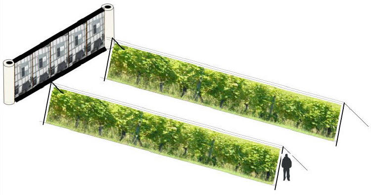
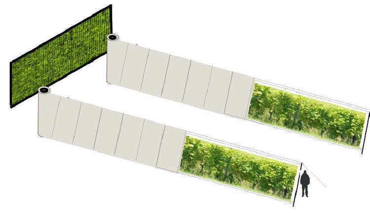
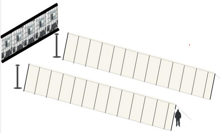
In essentials, the new trellising system takes the form of two structures in the shape of (isosceles) triangular prisms, the inner and outer layers. The outer layer provides support for sheet materials (principally plastic sheeting, but also including solar protection sheeting for very hot conditions and netting for protection of crops against pests, particularly birds.) It also comprises equipment for bringing the sheet material into position when the sheet material is needed from a storage / dispensing drum, and the means to return the sheet material to the drum when the sheet material is not needed or it would be inadvisable to leave it in position, as when very severe winds are forecast.
With the essential addition of a drum for storage and a mechanical means of moving the sheet into position and the replacement of the curtain rail by a very strong wire running the length of a row, this is a system with similarities to the domestic curtain-on-a-curtain rail system.
There are two faces of sheet material in the sheet layer, making up the two sides of the triangular prism. Both expanses of sheet material are suspended from the upper sheet wire, the topmost of the three wires at or near the apex of the structure. The base of the sheet material of the two faces are secured to the lower sheet wires, which are very near to ground level. The distance between upper and lower sheet wires will be sufficient for introducing a degree of tension to the sheet material, preventing it from flapping in the wind, but is not the only method of introducing tension.
The objective of multi-functionality has been followed wherever possible and desirable. So, plastic sheet material in this system has the function of insulation, making frost damage less likely and increasing the growth rate of the crop, but is also important as a water collecting surface. The water collected from this sloping roof surface is diverted to gutters at ground level and from there to suitable storage containers, by gravity if the containers are below ground level, otherwise by pumping.
When the sheet materials are retracted, then aesthetic objectives are achieved - the unfortunate appearance of plastic materials is present no longer than necessary, or not so long as to give rise to strong objections. There are also important practical benefits. In established protected cropping systems, the crops can generally not be watered by natural precipitation. In this new growing structure, this is perfectly possible.
The sheet layer has components which make provision for minimizing the effect of wind. The structure can withstand winds of moderate force or somewhat greater but retracting the sheet will protect the integrity of the sheet and the integrity of the structure before damage by destructive winds.
The growing layer inside the sheet layer has the function of supporting the wires which are used for training the crop, if the plants are quite tall (vines, apple and pear trees, tomatoes, raspberries) and supporting the crop load. The upper growing trellis support wire is a main wire, above head height, running the entire length of a row, from which are suspended sloping support wires intersected by three horizontal support wires which may or may not run the full length of a row. A row may be interrupted by shelters or openings, which have multi-functionality: they provide ventilation and the means to enter a row or leave a row, perhaps to go from one row to another, without having to go to the end of a row, which is a necessity in established systems of trellising. They can also be used as temporary storage places for the crops harvested within the row.
The growing layer is also the site of material handling. An overhead conveyor wire runs the full length of a row, again, above head height, and can support containers suspended from it. These containers can be moved by hand or, more often, by a winch, the winch wire connected to one container or, more often a container-group.
The detailed description provided refers to the growing of single rows of crops, the single row structure but also gives information about multi-row structures, formed by combining two or more rows at a single site. Particular configurations of rows can have substantial advantages in certain circumstances.
The components which make up the
structure, eg wires with various functions, fixings, sheet materials, belong
to one or more structure-groups.
These are the structure-groups:
(1) The core structure-group. These groups are of two kinds: growing units, which will form the great majority of units, and non-growing units.
Growing units
These are made up of two layers. Each of
these layers takes the form of a long isosceles triangular prism, with the
same length but different widths and heights.
(1a) The inner layer is the growing
and material handling layer. At the apex of the inner layer is the
trellis support wire, which supports horizontal and sloping vertical wires -
these in turn support the crop, eg climbing grape vines, apples - grown as
espalier crops, not as widely spaced bushes or trees - tomatoes. In the
detailed description section, some alternative uses of the horizontal and
vertical wires are explained in connection with the use of the system as a
polytunnel substitute. The inner layer also comprises the overhead
conveyor wire for transfer of materials along the layer to
a collection area or from a distribution area to a particular place in
the growing area. The materials include, eg, harvested grapes / apples /
tomatoes as well as prunings from vineyard / orchard activities, biomass
which can be used for heating.
(1b) The outer layer, the sheet and
sheet support layer. At the apex is the upper
sheet support wire and very near to ground level is the lower
sheet support wire. These wires support sheet materials with various
functions, eg, when polythene or other suitable sheeting is put in place,
raising the internal temperature of the growing volume to protect
crops from frost, to increase the growth rates of plants or to enable a
wider range of crops to be grown (such as grape varieties which without
protection could not be grown in a cool climate). Other advantages to be
gained by the use of this sheeting: enhancing the well-being of
workers, collecting water for the purposes of water conservation. The
water collected can be used for irrigation of the crops, decreasing reliance
upon mains water. (When the sheet material is removed, the crop is
watered by natural precipitation.) Netting material can be used to protect
the crops inside the structure from pests.
Non-growing units
These have various possible functions. One is provision of shelter for employees of the operation and visitors to the operation. Shelter is provided in the growing areas which make up most of the rows, but shelter in non-growing areas is convenient and useful. Space is limited in these units - they have the same height and width as the growing units - but more spacious facilities for the same purposes can be provided outside the rows.
Non-growing units also provide a means for going from one side of a row to
the other without the need to go to the end of a row. The facility can be
used by people on foot as well as by mechanized transport, provided the
transport is small enough to use the facility.
(2) Tensioning connectors. Some of the wires which run
the length of the core structure group (the trellis support wire, the upper
and lower sheet wires) do not themselves extend beyond the triangular
prism structure in one variant of the design but are connected to ratchet
straps, which extend from the triangular prism structure to the
ratchet mechanisms, the means of exerting tensioning forces on the
wires to which they are connected.
(3) Anchorage structures. The
ratchet mechanisms are connected to anchorage
structures, strong, heavy structures capable of
withstanding any forces imposed upon them indirectly by the wires indirectly
linked with them. The anchorage structures may have one function,
withstanding the applied forces, or may be multi-functional, combining this
function with others - eg storage, places for the work of the operation,
supports for climbing plants with aesthetic benefits. Small buildings with a
variety of functions, eg storage of harvested produce, plant propagation
facilities, large water storage containers, gabions.
(4) Spools for storage of sheet materials, which are dispensed when needed
and taken back into the spool when not needed.
Detailed description
Detailed Description
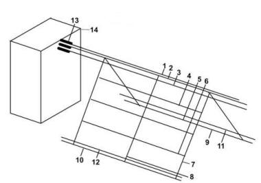
FIG. 1
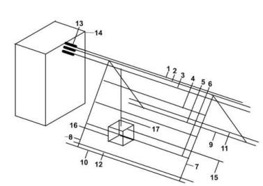
1, 2 and 3 are main wires. 1 is the upper sheet wire. Together with 11 and 12, the two lower sheet wires, it supports the sheet material, which is not permanently in place but may be brought into position when required. It may stay in position for considerable periods of time, as, for example, when rain or other precipitation can be expected fairly frequently over a period and capturing the wate,r by means of an impermeable cover for the outer layer, is one of the priorities. If watering the crops using natural precipitation is the priority - use of this water will reduce or eliminate the need for irrigation using mains water or collected water - then the sheet material can be withdrawn. The operator is able to decide on the necessity or otherwise of using sheet materials. Both upper and lower wires assist in withstanding wind gusts and other forces but the upper wire is responsible for carrying the load of the sheet material and will be correspondingly of much greater diameter.
2 is the main trellis wire, supporting the lower trellis wires 4, 5 and 6 and the load of the crops growing on the trellis. The main trellis wire and the two lower trellis wires 9 and 10 maintain the sloping wires in position and in a suitably tensioned state.
This drawing shows a 'growing unit.' Growing units are bounded by two sloping wires, eg 7, with a further sloping wire, 8, in the mid-position. This wire is the growing unit mid-point wire. In the case of climbing plants, a growing unit is used for growing one plant, eg a grape vine, a dwarf apple tree or a tomato plant. The exact width of the growing unit, and, therefore, the positioning of the sloping wires, is determined by the end-user. The grape vine, apple tree, tomato or other plant, is planted at the base of the mid-point wire. The plant is trained up this wire, with ties to maintain the plant in position. As it grows, the lateral growth chosen to remain is secured to the three horizontal wires. Other lateral growth is removed.
In this system, training grape vines and apple trees and other plants which undergo lignification should be carried out with the aim of producing plants whose lignified growth corresponds so far as possible with the positioning of the wires - for example, to produce a cordon which corresponds so far as possible with the position of 8. Divergece is permissible, so long as the plant is producing a form which enhances the structural advantages of lignification described next. As these plants mature and produce lignin, their structural strength and their ability to self-support will steadily increase, their dependence upon the sloping and horizontal wires will steadily decrease, with various advantages, such as the ability to withstand wind forces when protective plastic sheeting is not in position.
3 is the overhead conveyor wire, which can be used for transporting a range of materials besides harvested crops.
In Fig. 1, wires 1, 2 and 3 are shown as continuous from the anchorage structure 14, to the beginning of the row and along the row to the termination of the wires at the opposite end of the row. The termination is at ratchet straps which are part of ratchet mechanisms. Instead of the configuration shown in the diagram, there may be advantages in a marked change at the left boundary of the row. In this case, to the left of this boundary, the tensioning connectors are not wires but ratchet straps.
When alternatives are available, some are classed as permissible for the purposes of this invention some are deprecated but possible, some are to be regarded as completely inadvisable, but the focus here is upon optimal choices. Tension of the wires which run the length of a row of growing units is maintained by ratchet straps connected to ratchet mechanisms in the optimal configuration. Whether wires or ratchet straps are used, however, the connection to the anchorage structure 14 is made by means of ratchet mechaisms, 13.
When ratchet straps are used in this way, they may be multi-functional. Strong ratchet mechanisms are used - a rating of 10 tonne would be in excess of requirements in most circumstances, but would have advantages, since ratchets of this rating have ratchet straps which are broad. These straps, when used flat in the horizontal plane, can play a part in supporting roof materials such as polycarbonate which can form the main part of a simple shelter, one which can be quite extensive and as such, of considerable value.
These and other wires will be of a diameter which can withstand the anticipated forces, with a safety margin included. It is not envisaged that a single wire of sufficient (more than sufficient) diameter will be used in all cases. Operators will wish to avoid unnecessary waste and if it happens that they have a stock of usable wire less than the optimum diameter, then two or more lengths of wire can be used, if due diligence is employed, including professional advice when necessary. The strength of a rope comes from sophisticated manufacturing techniques, including twisting of components. The combining of separate lengths of wire to accomplish a particular purpose will sometimes be permissible and sometimes not.
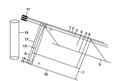
FIG. 2
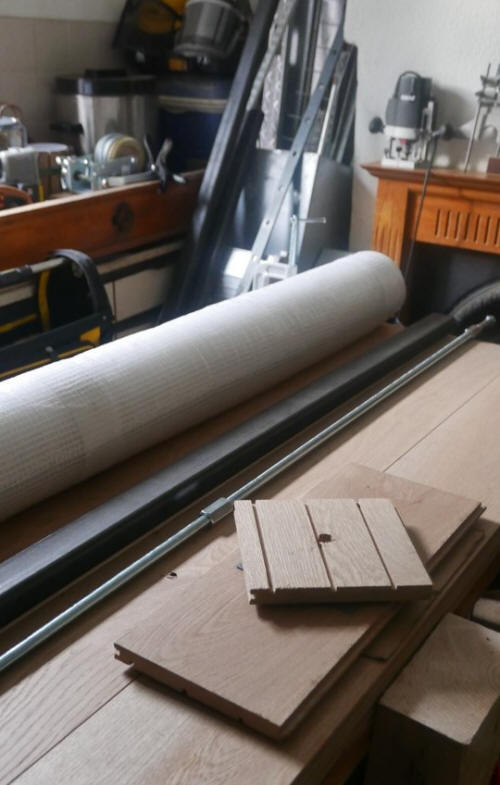
This drawing includes the same components as FIG. 1 but without the anchorage structure and with additional components, which serve to maintain in position and to tension to a suitable degree sheet material. In this example, polythene is the sheet material. 16 shows a sheet material spool, one of two, used for storage of sheet material and for dispensing sheet material at this end of a particular row. The twin system provides sheet material 8 for the two faces which make up the outer layer triangular prism. The materials are stored in a vertical position but are dispensed to faces which have sloping supports. This presents no difficulties.
When sheet materials are dispensed, the spools must be free to rotate without excessive frictional forces. The roll of sheet material is part of an assemblage which includes a turntable of sufficient size. However, this turntable need not have an elaborate system of bearings or other sophisticated mechanism, such as a motorized turntable. The turning of the turntable can be assisted by the provision of bars - fairly long bars - which make the assemblage into a form of capstan, these longer bars reducing the force needed to turn the turntable.
Rotation of the turntable may also be assisted by the action of a winch, located inside the inner growing layer some distance from the sheet material storage spool. A wire (or synthetic rope) from the winch is connected to a gripping device put in place at the end of the sheet material before action begins to bring it into position on the sheet layer. The gripping device may take the form of two vertical bars on either side of the sheet material which can be brought close together by means of a simple wing nut and bolt system or similar means.
This drawing shows the fastening of the sheet to the supports in the outer layer and a method of maintaining tension in the sheet so that it is better able to withstand wind forces. 1 is the upper sheet wire, 8 is one edge of the sheet material, in this application of the system, a plastic material such as polythene. There are rows of eyelets in three horizontal bands, upper middle and lower, only two of the eyelets (on the upper and lower bands) shown here.
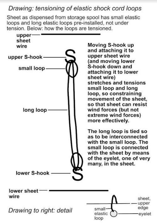
The sheet material is attached to the upper sheet wire 1 and the lower sheet wires 9 and 10 with pre-placed fasteners already in place. In the case of plastic material, they are pre-placed at the upper and lower eyelet rows on the sheet material. 14 shows an eyelet on the lower row of eyelets and 15 shows an elastic loop These loops are pre-installed on the plastic sheet so that when the sheet is moved into position by the winch and rotation of the storage spool, the eyelets are available for use. These loops are connected to the upper and lower sheet wires with simple fasteners, such as metal 'S' fasteners.
These metal fasteners are rigid and would not secure the sheet to the wires adequately if used alone. Wind forces can move the sheet but after yielding slightly, a plastic sheet will tear. The loops, formed of elastic shock cord, yield much more but can resist wind forces well.
Polytunnels are so designed that the sheet material is kept in tension, enabling the material to withstand wind forces to a large extent, but not so much tension as to damage the material. The system used in polytunnels allows movement to a certain extent. It is not completely rigid or inflexible.
In this growing / water collecting and conservation structure, there are much longer loops of elastic shock cord 13 than the small loops 15. These will be stretched by wind forces but will recover, enabling the sheet to withstand the applied forces. The elastic shock cord maintains the sheet material in tension. The degree of tension achieved in a polytunnel system is unattainable but will be more than adequate to withstand wind forces which are not excessive, without damage to the plastic sheeting. The system has been thoroughly tested and it has been concluded on the basis of the evidence obtained that the system offers a high degree of protection. It cannot protect in cases of severe winds, when polytunnels may be damaged or destroyed and buildings too may be damaged or even destroyed, but the system has the great advantage that when very strong winds are forecast, the plastic sheeting can be wound onto the storage spool.
FIG. 3
This shows the basic structure of the inner layer, the growing and materials handling layer. Various methods of transferring materials will be used inside the structure and outside the structure. Inside the structure, the overhead conveyor wire 3, which runs the length of a growing row, provides a convenient way of supporting loads 16, suspended from a wire 17 secured to the overhead conveyor wire. The loads which are supported and transporting may be quite heavy. The loads are moved by a wire 15, in this case to the right. Securing a wire to the opposite side of the load gives a means of moving the load to the left.
Convenience in transportation is not the only advantage. Workers in vineyards and orchards commonly carry loads which are excessive and which can lead to injury. Containers suspended from the overhead conveyor wire can hold harvested crops until they are moved, with no need to weigh down the worker. The distance between the grapes or apples growing in the structure and the container which takes the harvested product is very small, one of a number of ergonomic advantages in the system.
When the harvesting is complete in that section of the growing structure, then the loads can be moved. This is achieved by attaching the winch wire (alternatively, winch rope) 15 to the containers, which are connected with each other. The workers stand behind the containers so that when they move, they are in no danger. They will give an instruction to a winch operator, who begins operation of the winch. A hand winch is completely adequate for this purpose, since the distances are not great and the loads not in excess of the capabilities of a hand winch. A hand winch will be portable and when work is started on the next section of harvestable produce, then the winch can be moved, ready to transfer the new loads.
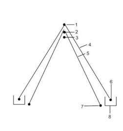
FIG. 4
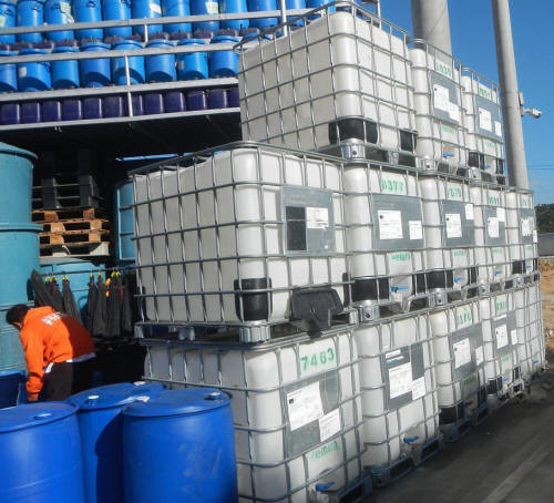
This drawing shows a side view of the inner and outer layers and, below the lower edge of the sheet layers, gutters. 4 is a sheet layer, secured and tensioned by the upper sheet wire 1 and the lower sheet wire 6. 5 is part of the trellis growing structure, supported by 2, the main trellis wire and the wires which rely upon 2 for their own support, and also secured and tensioned by 7, the lower trellis wire. 3 is the overhead conveyor wire. 8 is a gutter. The gutters receive the water which runs down the two faces of plastic sheet material. The gutters transport water to water collection facilities, from where the water can be pumped to water storage facilities, such as Intermediate Bulk Containers. Water may well be able to reach underground water storage containers without the need for pumping.
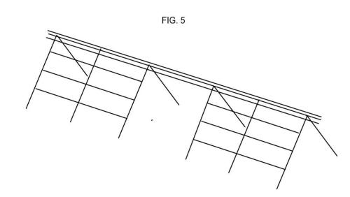
FIG. 5
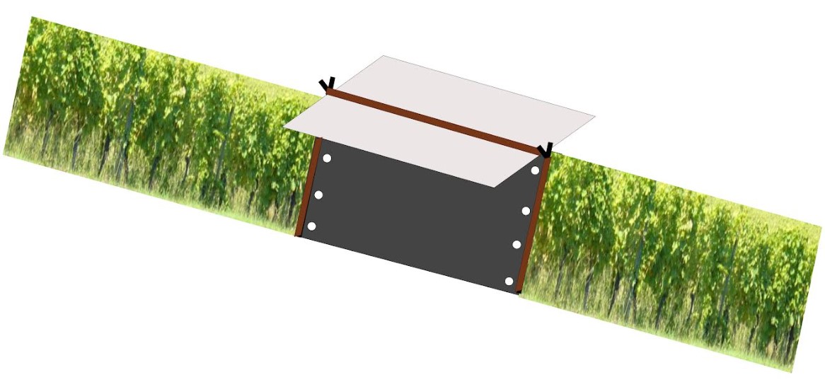
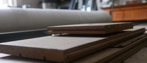
This drawing shows at left and right growing units and between the two a non-growing unit, which has the various possible functions already outlined. The overhead wires (above head height) are not interrupted but the trellis wires which support the plants are interrupted. Obviously, if they were left in place, it would not be possible to enter the unit or leave the unit. The sides of the non-growing unit may be left open but more often, there will be plastic sheeting sides available which can be rolled up or down or plastic sheeting or other material which covers some but not all of the two faces, with a door on each side and if desired windows on one or both sides. The decoration and furnishing of a non-growing unit are a matter for the end user but the choice is wide. The surfaces may include oak, larch or other panelling. The aesthetics may blend in with the vernacular architecture of the area or form an arresting contrast.
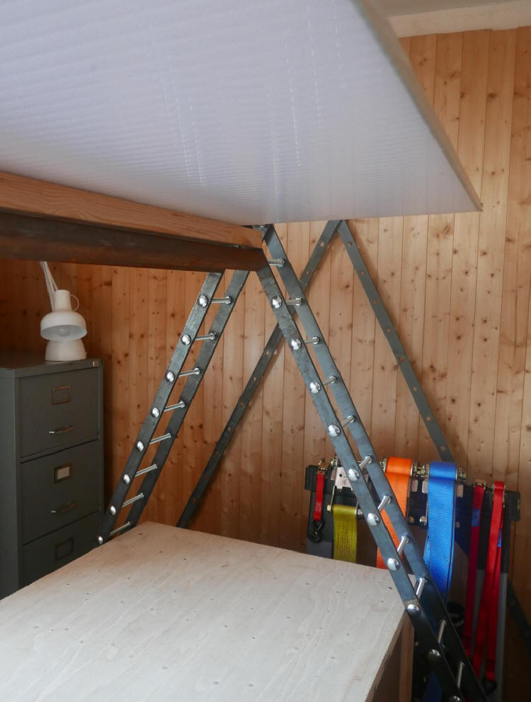
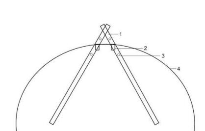
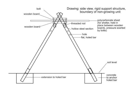
FIG. 6
The drawing gives a side view of one of the boundaries between a non-growing unit and a growing unit, looking in the direction of the growing unit. The components shown belong to the non-growing unit. Growing units require structural integrity and strength of a kind and to a degree which can be provided by wires of different diameters and other physical properties. In a non-growing unit, there is a need for structural strength and rigidity which can best be provided by rigid components complementing support by means of wires.
The drawing shows an implementation of a design which makes use of strong perforated steel bars 1. The perforations go the length of the bars. Only some of the holes are shown in this drawing, including 3. In the drawing, two of the circular holes in the steel bars are used for securing the ends of threaded steel rods. These are commonly 1 metre long and to span a longer length, the rods are joined with metal connector nuts. Rods joined in this way will sag a little towards the centre, but provide a degree of rigidity which is beneficial for this part of the structure. The security is very much increased by the fact that the two lengths of threaded rod are each inside a length of steel section 2 (without perforations).
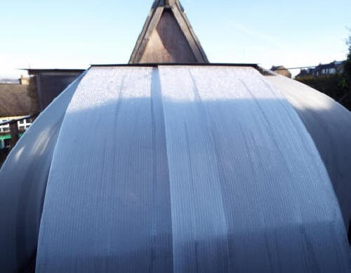
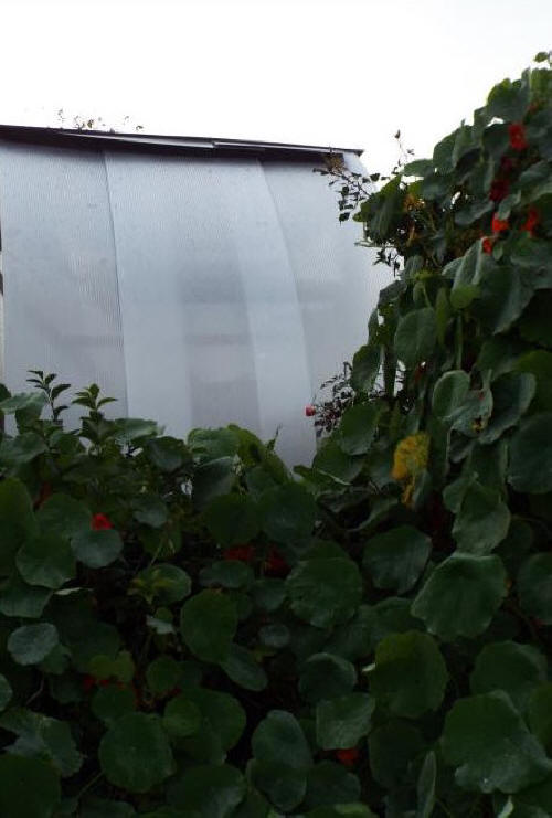
The two lengths of steel section support a length of timber, giving a means of keeping in place, if desired, polycarbonate sheeting 4, which gives a further method of forming the walls of non-growing units. The polycarbonate sheets are secured at the base (a simple system of stakes is sufficient for this purpose), the support stakes so placed that the polycarbonate sheets are curved. In this curved state, they are very resistant to wind forces. Like the plastic sheeting employed for the growing units, these polycarbonate sheets are easily removed if very strong winds are forecast but their ability to withstand strong winds is very considerable. Polycarbonate with different opacities and degrees of light transmission are available to prevent or reduce excessive heating. Shading materials can also be applied.
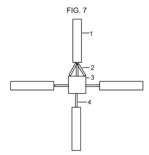
FIG. 7
The drawing shows one hypothetical way to place rows, purely for illustrative purposes. Commercially, large or very large numbers of rows could be used, with substantial advantages, such as economies of scale, and the substantial contribution that large arrays could make to water collecting and conservation / the mitigation of drought.
Probably, the very small array shown in the drawing would not be used in the commercial growing of grapes, apples or vegetables since, even if the four rows were very long, this configuration would not make good use of the available space, but it could be used in the setting of a large garden, where practical growing is combined with other activities, such as the growing of ornamental plants. The spaces around the rows could be lawns or a semi-wooded area. There are obviously many other possibilities.
In the centre is 3 the anchorage structure. 1 is a constituent row, one of four rows in this case. 2 shows some ratchet straps. Their principal function is support of wires and maintaining tension in wires but they may also be used to support simple roofing materials, to form a shelter. 3 will also be multi-functional in many cases. It may be a small building. It may be two Intermediate Bulk Containers placed one on top of the other, for water storage. It may take the form of gabion containers with sufficient height and overall bulk to be able to withstand the opposing forces from the wires. All of these may have aesthetic as well as practical functions. Intermediate Bulk Containers take the form of a large plastic storage cube, often storing 1000 litres (1 tonne) of water, inside a strong framework. Gabion containers take the form of a cube made of strong metal wire containing rocks or other materials.
Climbing plants, such as the very vigorous vine Vitis vinifera Brandt or Humulus lupulus 'Aureus,' the golden hop plant, grow very well when given such a framework. They disguise the framework in doing so. These plants will climb up small buildings as far as roof level - a much easier way of implementing a 'green roof' than lifting tonnes of soil or other growing medium to the roof and sowing plants such as species of Sedum there.
Alternatively, the anchorage structure may be a building of considerable size, perhaps of more than one storey. It may be a winery, containing all the necessary equipment and supplies for making wine from the grapes - but a winery which also acts as an anchorage structure, securing the wires from the crop rows. As in the case of smaller structures, climbing plants may be used to enhance the appearance of the structure.
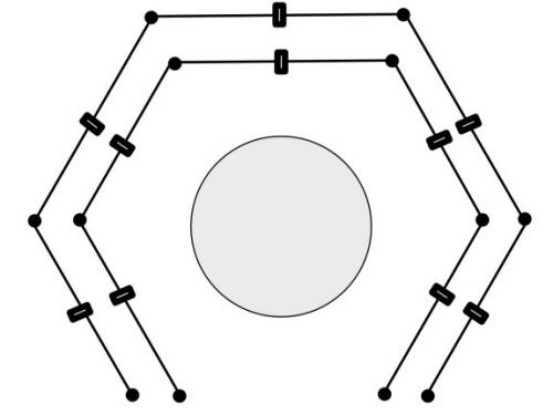
In the drawing, of the four growing rows two are oriented West - East and two are oriented North - South. The usual recommendation is to plant North - South if possible, since this configuration gives the most efficient interception of solar radiation for the growing plants, but the scheme is commonly not followed for one reason or another. One good reason to plant in a West - East orientation for any growing operation which involves crop protection and enhanced growing by means of plastic covers is the fact that the prevailing winds may well come from the West. The West - East orientation minimizes the risk of wind damage. In the diagram, it is likely that growing units in the row to the East of the anchorage structure will have greater protection from the wind that the other rows, in the most common weather patterns, but the protection offered by a building or other structure will obviously not protect a complete row.
The choice of a grid configuration for the rows makes available many possibilities. For example, if rows running North-South are preferred, with the further preference that the vineyard should resemble one of the vast number of vineyards which have ordered rows without nearby buildings or with buildings out of sight, then one choice would be a long anchorage structure running West-East and, quite some distance away, a similar anchorage structure also running West-East and to the South of the first structure, both structures hidden by hedges, and in the expanse of land between the two, the long rows of vines, apple trees or other plants which are grown, the wires from the rows passing through the hedges to the completely or partially hidden anchor structures. The anchorage structures could have only this function, support and tensioning of the wires, or could take the form of multi-functional long buildings.
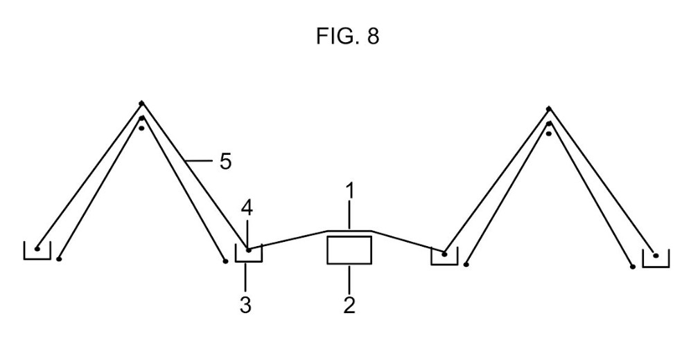
FIG. 8
When plastic sheeting is installed on the rows of growing units, a water-collecting surface is available which may be very large. The more rows and the longer the rows, the greater the surface area available for water collecting. However, it is also possible to install water collecting surfaces in the rows between the growing units: the inter-unit row sheets.
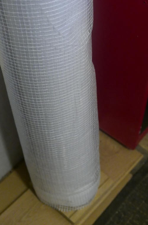
The material of the surface may be different from the material which makes up the material of the sheet layers on the growing units. In the case of these units, scaffold sheeting is a strong and cost-effective material, equipped with rows of eyelets which allow ready fixing of the material to the upper and lower sheet wires by means of elasticated loops. The same material may be used for the inter-row water collecting sheets, if the width of the sheets is suitable to cover the width of the inter-unit rows, allowing for the raising of these sheets in the centre. Using more than one scaffold sheet, side by side, gives a means of covering greater row widths. As an alternative to light-transmitting materials, a different material may be used, such as opaque tarpaulin (tarp) material.
The water collected by the units of the growing system and the inter-unit rows will together form a very substantial part of the total precipitation falling on the area of the vineyard, orchard or other farming operation where the system is employed, making a very valuable contribution to the operation and even for water uses outside the operation. When the sheeting is removed from the growing units, natural precipitation can water the crops in these units. In this case, water collecting from the growing units is not possible bet there is a valuable contribution to water conservation., since there is no need to use irrigation water or the demand for irrigation water is reduced.
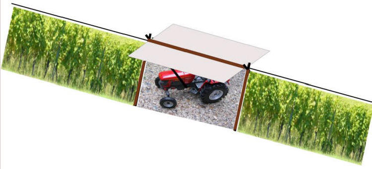
As in the case of the water collecting facilities provided by the growing units, the inter-row water collecting facilities will not be in place at all times. In fact, it is likely that the inter-row facilities will be in place only when protracted periods of plentiful precipitation are anticipated. When the inter-row sheet material is in place, then no vehicles can use the rows. Pedestrian use is possible but should obviously be minimized, to avoid undue wear of the sheet material. The end user has the decision as to when and if to put in place water collecting sheet material on the growing units and inter-unit rows, and the decision as to when and if to put in place sheet material of other kinds.
When inter-unit row material is in place, pedestrian traffic can still use the growing units. There is no sheet material on the ground within these units. Powered vehicles can also travel along the unit rows. Very small tractors are available which can use the interior space without difficulty, but only tractors powered by electric motors are possible, for the obvious reason that exhaust fumes from tractors in the interior of the units are not permissible.
In FIG. 8, 1 is the water-collecting sheet material for the inter-unit row, which must have eyelets on the sides of the long expanse of material. These eyelets are secured to the lower sheet wires 4 by means of elastic shock cord, as used to secure the lower ends of the water-collecting unit sheet material 5 to the lower sheet wires.
In the centre of the inter-unit rows are supports 2 for the inter-unit sheet material. The supports will form a continuous raised structure running the length of the inter-unit row. This support structure tensions the sheet material and raises the sheet material at its centre, so that water can run down the surface into the gutter 3 by gravity.
The supports can be made from components in a variety of materials. It is essential that the components which make up the support structure should be easily movable, by suitable tractor equipment or in the case of some components by muscle power. Some possible supports: straw bales, pallets and specially designed (but simple) supports of wood, lightweight metal or plastic. If straw bales are used, these will be protected by the sheet material from precipitation. An impermeable covering will also be needed between the straw bales and the ground. The inter-unit rows could in some cases constitute a useful storage area for straw bales. Straw bales may already be used by the orchard, vineyard or farm. They can play a useful part in the operation, even if use of the inter-unit row for storage is not desired. Straw bales can be used, for example, to release heat energy in modern straw-burning boilers. These boilers can also make use of prunings, generally available in large quantity from a vineyard or orchard. Amongst the possible uses of the heat energy released by burning biomass is warming the interior of growing units. Large diameter pipes can direct hot or warm air from a boiler facility to growing rows for frost protection. The increased carbon dioxide concentration of the air in the interior can increase the growth rate of plants, if only marginally.
The sheet material used for inter-unit row water collecting has other possible functions. It can assist in weed killing in the inter-unit rows. If light-transmitting sheet material is used, it can suppress weeds by solarization, over-heating of the weeds as well as weed seeds at or very near the soil surface. If opaque sheet material is used, it can suppress weeds by depriving them of light.
The long gutters below the lower edges of the expanses of water-collecting material can easily direct water to water-storage containers (which must necessarily be of large or very large capacity) if the ground slopes at a convenient angle along the length of the gutters. This will not be realized in practice in most cases.
If the surface of the ground is undulating, irregular, with many hollows, perhaps deep hollows, there are methods of implementing water storage facilities which can receive the water collected by the surfaces. For example, pools or small ponds lined with impermeable material can collect the water at various points along the guttering system. Gutters can be modified to form 'deep gutters' and 'variable height gutters' which can collect water in low-lying areas.
In the case of ponds, the water can be stored there for a considerable time but in most cases, the water collected in places other than the main water storage containers will need to be removed and directed to one or more main water storage containers and this water will need to be pumped. The interior of the growing units is large enough to contain suitable pumps and their pipes. The pipes can when desired remain in situ inside the units. The part of the interior at the base, near the sloping sides of the units, will in most cases be available for use. This area forms a convenient usable space for lengths of water piping.
If the operation making use of this system is one which has a particular interest in aesthetics and ornamental plants, then the water in low-lying areas which cannot reach a water storage container by gravity can serve a valuable function. Ponds can be constructed in these areas in which the water is replenished by the water received, eliminating or lessening dependence upon other sources of water, such as mains water. Aquatic plants and bog plants can flourish in these areas and there are many benefits for wildlife.
Commercial operations where the growing of food plants is the focus and collecting water to irrigate food plants (or other functional uses of water) is also a priority may also choose to implement ponds and bog areas in some cases.