As with the Home Page of the site, scrolling down the page will
give a quick view of the varied material to be found on the page. The
material on design and construction is dispersed. It can also be found on
other pages of the site, for example the Home Page and the gardening pages.
Some of the more recent design / construction projects have not yet been
documented in any detail.
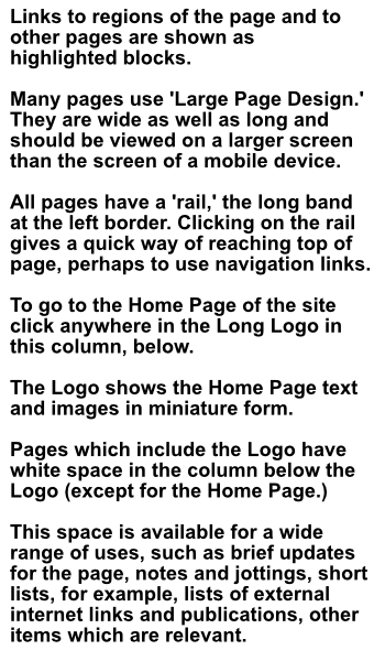
The greenhouse and its extensions
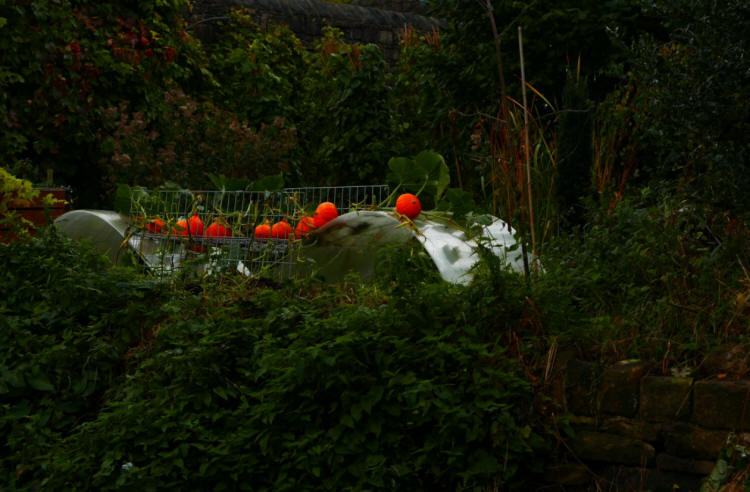
Pumpkins of the variety 'Rouge Vif d' Etampes,' supported on the roof of
the West extension of the greenhouse. There are climbing plants on the roof
of the East extension too, a grapevine, growing in soil inside the
greenhouse, and hop plants, growing in soil just outside the greenhouse. The
East extension also collects rainwater, stored in a container nearby.
In the photograph above, the triangular roof of the main
greenhouse structure is clearly visible beyond. The roots and lower stem and
foliage of the plant are inside the solar composter, which is part of this
extension. The solar composter speeds up the breakdown of material,
producing compost more quickly by the heating effect of solar radiation. The outer wall of the
solar composter is of polycarbonate sheet, like the walls of the main
greenhouse.
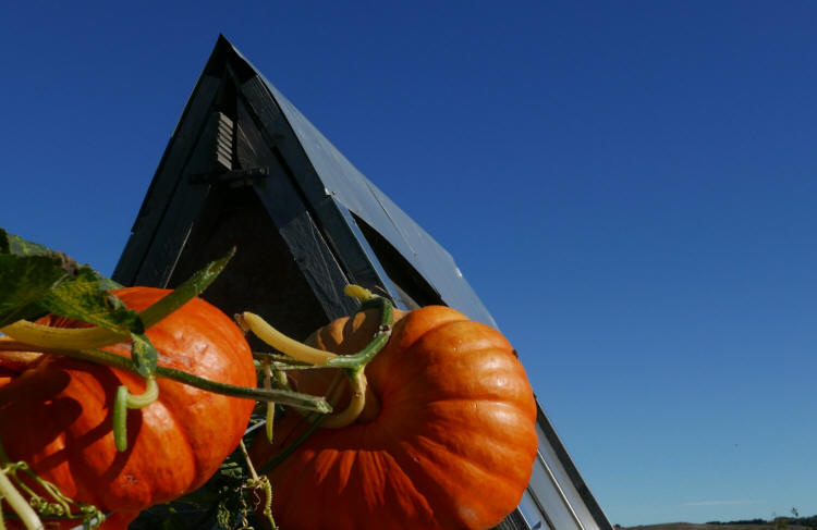
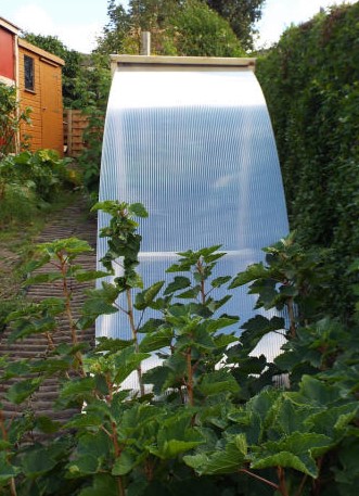
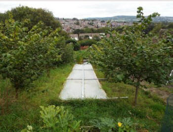
Above, the PHD solar composter
viewed here from the lower allotment. The solar composter is one of the extensions to the
greenhouse: a large composter, with polycarbonate sheets
on all sides. The composter is a 'walk-in' structure. It has plenty of internal
space so that the compost can be turned (with a manure fork) very easily.
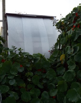
Below, view into the interior of the composter, after removal of the door,
which is made of flat polycarbonate sheeting. The compostable materials are
covered with flat polycarbonate to increase insulation.
Photograph taken a
few days after the design idea, which was followed by very rapid
construction.
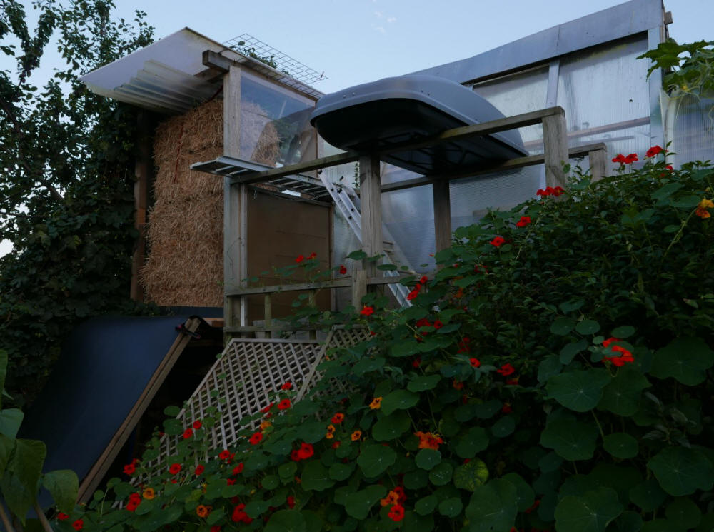
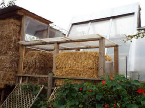
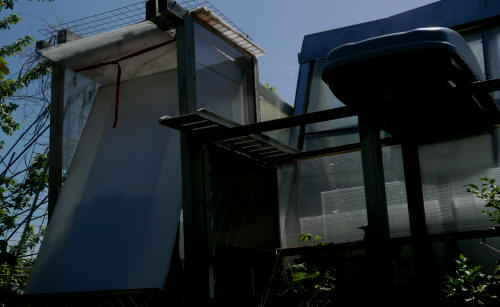
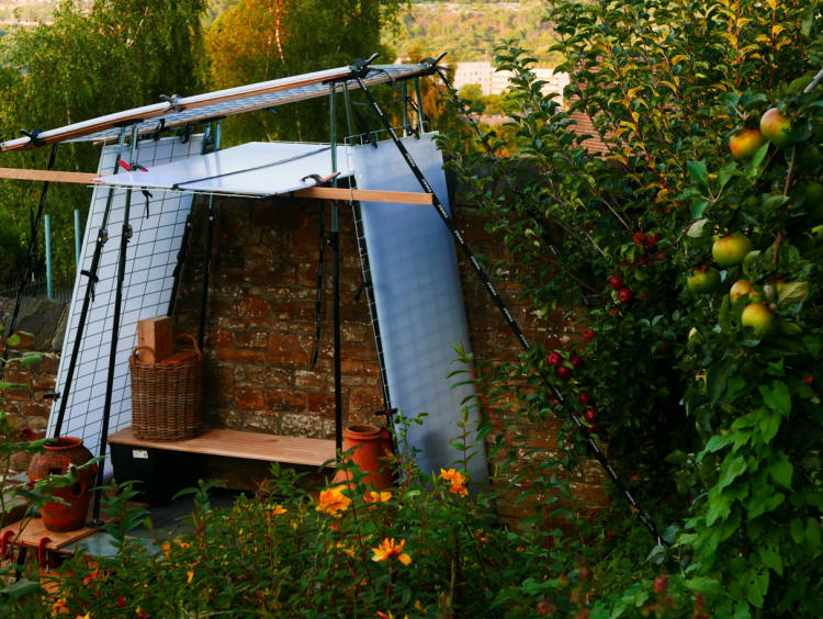
Above, the North side of the main greenhouse structure, triangular, with
a sheet metal roof and on the left, the East extension of the greenhouse,
with a flat / sloping roof: it uses the new roofing system I've devised. It
took very little time to construct and has many advantages. The top layer is
flat. This isn't the main waterproof layer which protects the extension from
the elements - this layer is lower and is sloping. In this position it's
within the walls and protected from wind damage. Water falling on this
sloping layer falls on the black sloping layer at the left and runs into a
collecting container, not visible here.
The north-facing wall of the extension is constructed from straw bales.
The wall can be coated with lime plaster, as in straw bale buildings, but I
prefer to leave it uncoated. I like the look of barley or wheat straw. The
straw bales keep their appearance, and their protective function, for years.
Clearly visible, in front of the main greenhouse structure the storage box, ladder and aluminium platform
which gives access to some of the green roof. Prominent,
climbing Nasturtium (Tropaeolum majus) plants in flower.
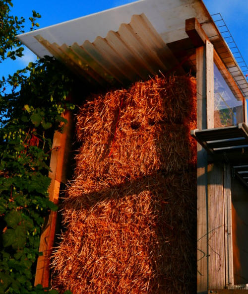
Above, two views of the straw bale wall, details. Most of the plastic sheets
which form part of the new roof design are hidden within the structure. The
parts which project aren't aesthetically pleasing but components are
available which hide them, whilst still allowing them to function as
water-collecting and water transfer surfaces.
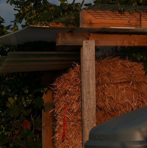
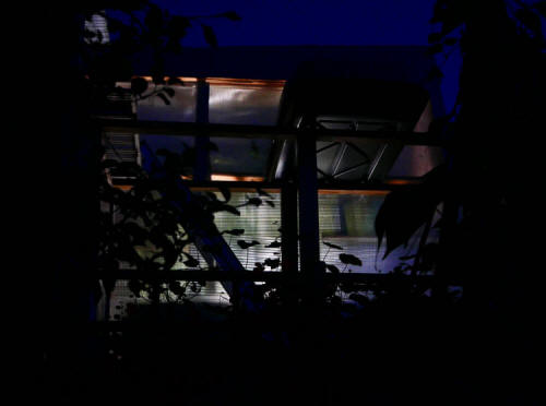
Below, view of upper section, North side of the greenhouse:
Above, a less recent photograph of the North side of the greenhouse,
showing storage of straw bales.
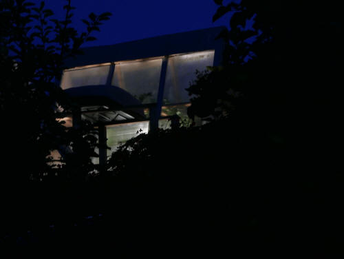
Below, two photographs of the North side of the main greenhouse structure
by night.
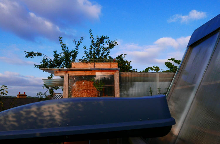
Above, a view of the West side of the greenhouse extension. A closer look at part of the new roofing system and the upper part of
the straw bale wall. The wooden box on
the roof, seen from the side here, isn't an essential part of the basic
design. Its function is simply to increase the height of the climbing plant,
the part that has reached as far as this, so that it's displayed more
effectively. Visible also, the highest thing in the photograph, upper
branches of a plum tree, variety Marjorie's Seedling.
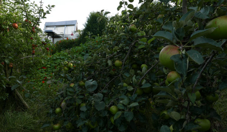
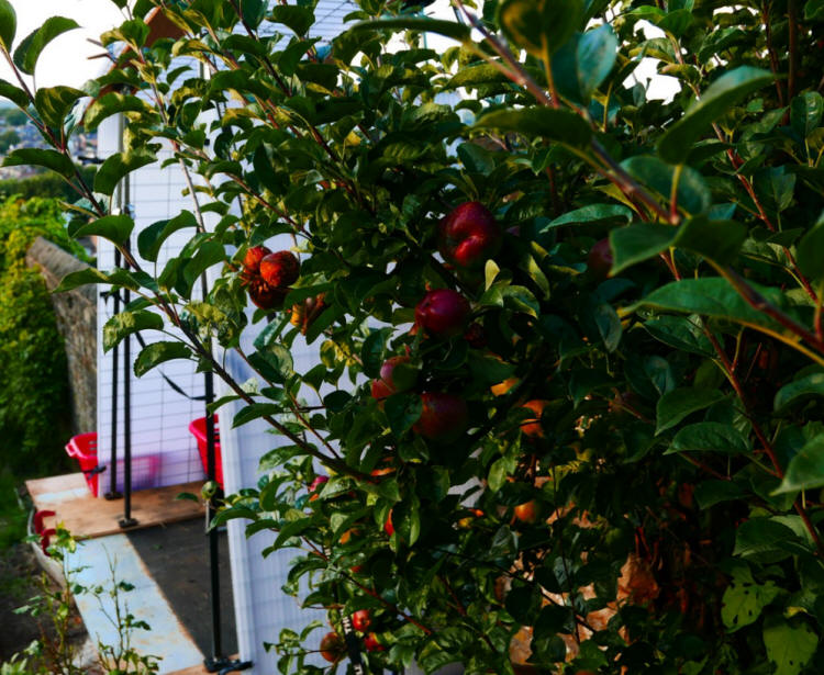
Above, view of the greenhouse from the orchard. On the left, Dabinett cider
apples, on the right, Bramley cooking apples.
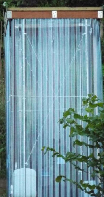
Above, view of a temporary polycarbonate structure for protected
cropping in the upper allotment. This and similar structures can be
installed and removed very quickly and easily.
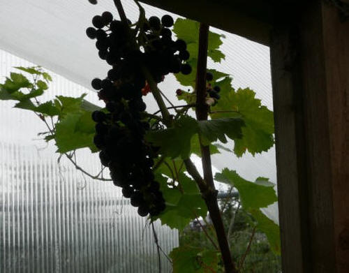
Growing in the East extension of the greenhouse, a vine of the red grape
variety 'Regent.' The vine has been trained and the upper growth is on the
roof. This green roof supports the upper growth of a hop plant as well. This
method of implementing a green roof, a roof which supports the upper growth
of climbing plants, is far easier than green roofs of the usual kind, which
need the transportation of large quantities of soil / compost to the roof
area. More
information below.
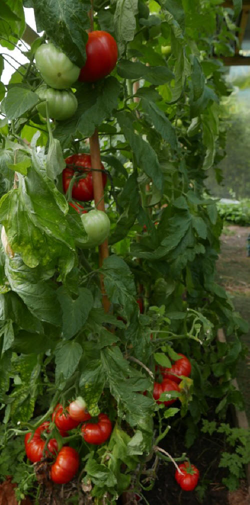
The main greenhouse structure is used only for growing tomato plants,
except for some Basil grown earlier in the year. All the tomato plants are
grafted plants, which have very substantial advantages - in particular,
their heavier yield and their resistance to soil-borne diseases, even when
the compost is used for years.
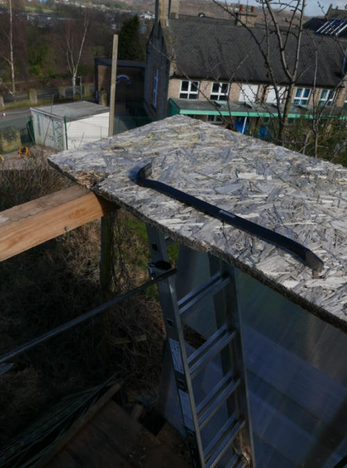
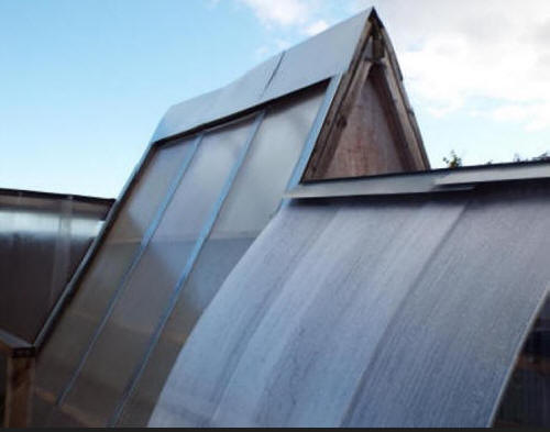
The roof of the new roofing system of the East
extension. It's vastly superior to the roof it replaced, part of it shown
here, before removal of one of the OSB3 sections. These sections supported
sections of sheet metal. The roof was flat. To make the roof pitched, so
that rainwater could drain away easily, would have involved prohibitive
effort at the time. i installed the roof after a long, hard day of work and
used just enough screws (self-drilling wing tip screws) to secure the roof.
To have used all the screws needed for permanent security was out of the
question. I was working at a height and so fatigued that i would have risked
an accident. Not long after, before I
could complete the work, very strong winds caused severe damage to the roof.
I decided not to use a standard design. The panel
used is light-transmitting, raising temperatures in the
space below by the greenhouse
effect. I use it for storage - the drier atmosphere prevents or restricts
rusting of garden tools stored there - but it can also be used for growing
plants. This design makes it very easy to introduce pitch, to construct a
sloping roof rather than a flat roof. Wire mesh panels above the corrugated
panel allow for support of climbing plants, in this case a hop plant and a
grape vine. An opaque horizontal roof layer can be fitted below the sloping
water-collecting layer and the layer can be of various materials, such as
plasterboard. This prevents the use of the space for growing plants, or
makes it less efficient for this purpose, but it's a way of making the
interior look like a 'standard' interior, not the interior of a greenhouse
extension.
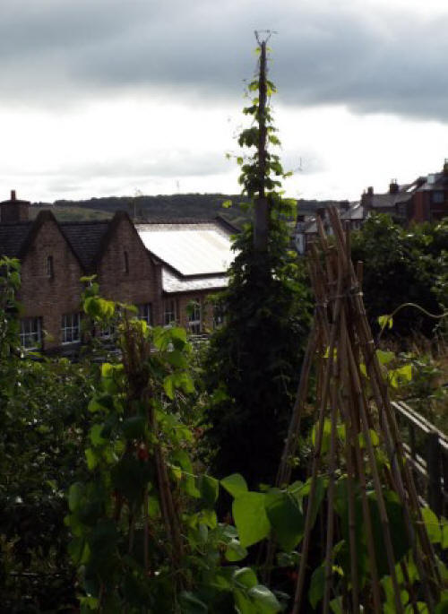
The roof design makes it easy to grow climbing plants, provided that
the plants are tall enough for their top growth to reach the roof area, This
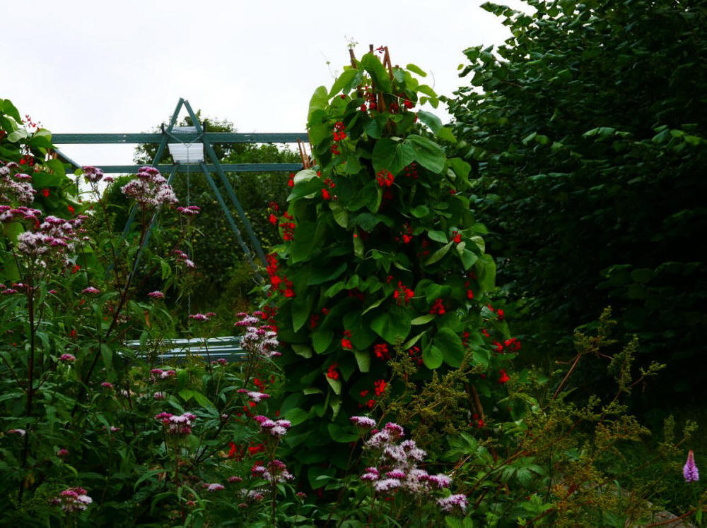
is the case for the hop plants and the grape vines I grow. Before this new
system, I grew the hop plant near to the north and east sides of the
greenhouse up a vertical support, to make a 'hop spire.' This is shown in
the photograph above, with runner bean pyarimids in the foreground.
More information on the top layer of the new roofing system, the mesh
panels above the polycarbonate and PVC layers. These mesh panels support the
upper growth of the climbing plants, to form the 'green roof' layer.
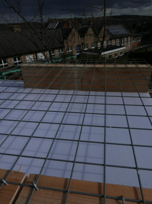
Part of the wire mesh panel which supports some of the growth of the
plants of the 'roof garden.'
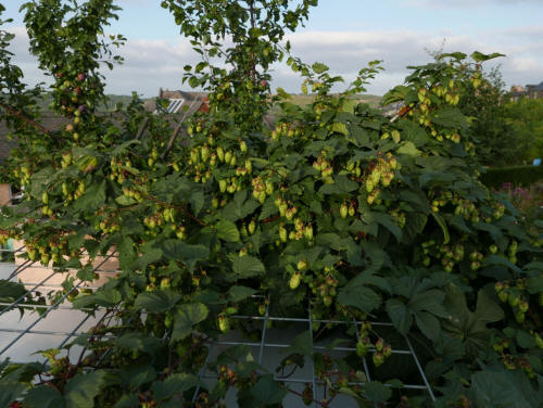
Growth of the hop plant, variety 'Target,' on the roof.
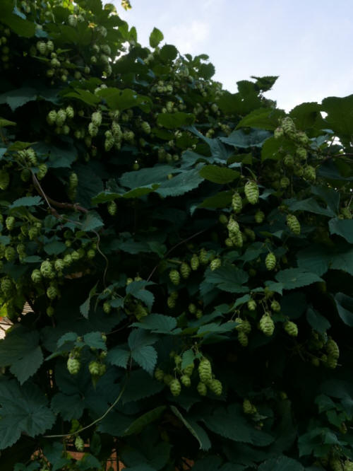
The hop plant had to be trained to climb from ground level to the roof
extension. The hop plants would have been unable to climb the vertical
polycarbonate walls of the extension. I put in place a fairly
elaborate system of supports but none of it is visible here. The hop plant
using the support system has produced cones, usable in brewing beer.
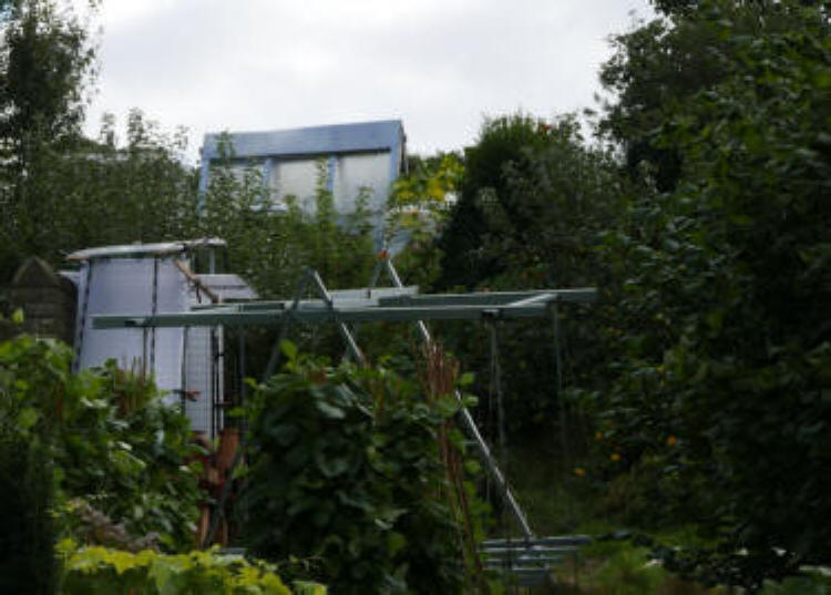
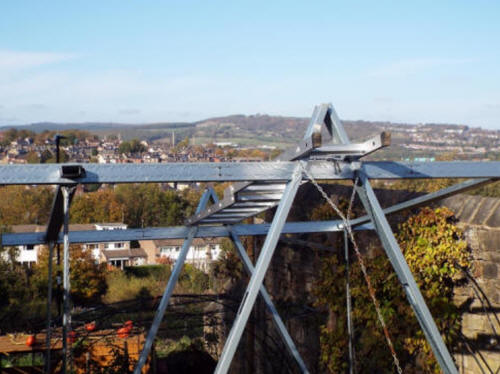
A view
The view is of some of the lower allotment, seen from the path leading
to the gates of the lower and upper allotment. In the foreground, one of the
platforms, with one of the metal storage containers for water.On the left,
gorse (Ulex europaeus) in flower - the gorse was planted by me - and the sheet metal roof of the small,
tall shelter on the platform. On the right, the versatile metal
structure and some apple blossom, variety: Spartan. Also visible, part of the long wooden path
leading to the pond of the lower allotment.

Two small buildings: a shelter / store
on the 'lower platform' and a replacement shelter/store on the same platform, with propagator
Obviously, the two small buildings can't occupy the same platform at the
same time. First, information about the original structures at this site,
then information about the replacement structures, a shelter with a large
propagator. This is followed by information about the other platform, the
'higher' platform - that is, higher up the slope of the allotment. The propagator panels can easily be removed so that the
extension can be used for storage of apples or other things. The new
structures are much simpler and easier to construct than the original
structures.
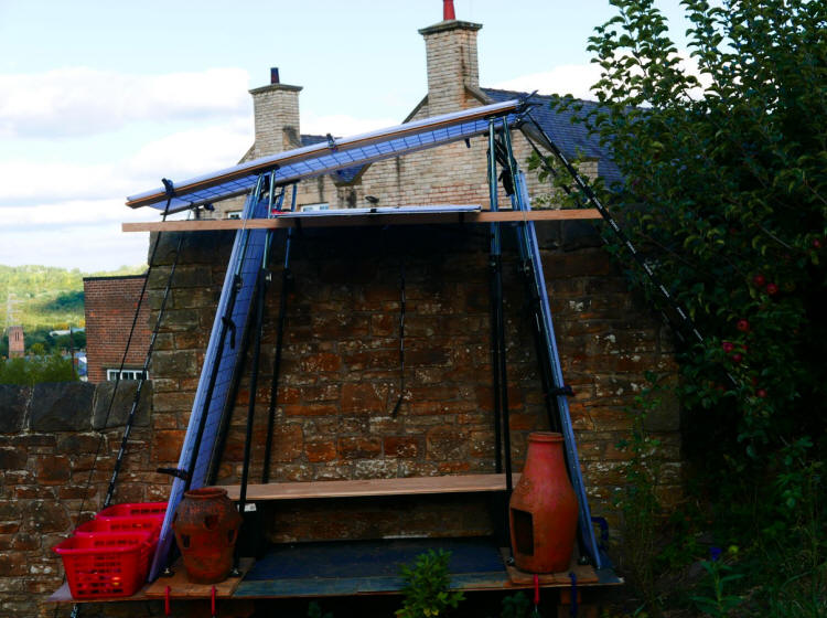
A new design, a versatile structure with many advantages. I make use of
mainly slender components, to produce a structure which has a light
appearance but has the strength to withstand strong winds, and, of course,
can stand without collapsing. The tubular metal supports would fail, would
fall if it were not for the components which stop that from happening. I've
been careful to use more than one method of achieving this, to make use of
'redundancy.' Not all the components are light. The platform which supports
the structure has a fairly light surface, of plywood, sheet metal and rubber
matting but it's supported by scaffold boards, supported in their turn by
oak pillars concreted in the ground. The structure itself has only two
walls. There's no West facing wall. i wanted to have an uninterrupted view
towards the West. The stone of the long boundary wall supplies an East wall.
The stone wall has the advantage of thermal mass, raising the temperature
inside the shelter. Pots, not all of them visible here, supply contrast.
They're there simply because I like to see them there and because I already
had them available. Despite any apparent fragility, the shelter is rock
solid in strong winds. It doesn't move at all.
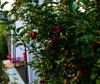
A photograph with nearby plants in bloom, roses and apples of a Dabinett
cider apple tree and a Bramley apple tree. I've planted four Dabinett trees
and two Bramley trees in the allotments.
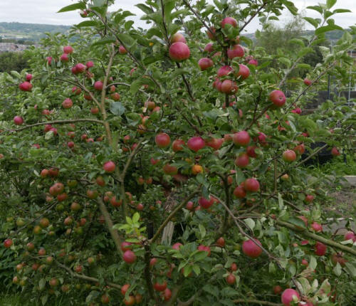
A closer view of some of the Dabinett apples.
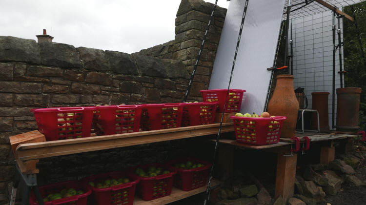
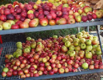
Apples in storage, mainly from three of the trees in the orchard, a Dabinett
tree, a Bramley tree and the Winston tree.
The relatively bulky objects on the platform floor form a contrast with
the slenderness of the shelter. I've begun to move rocks to the ground near
the platform and underneath the platform. These are intended to become
another source of contrast with the platform. The rocks come from the
allotment itself. Slightly further away from the platform are more rocks,
not seen in this photograph. These are rocks which have enough bulk
to give a suggestion of the parent rocks, which of course are the source of
soil. The rocks here are mainly from outside the area. They include Welsh
slate (not the thin roofing slate.) I intend to add to the geological
collection. Cotswold stone would be an essential addition. Of course, by far
the bulkiest and most prominent thing to contrast with the shelter is the
wall. Only a short section can be seen here.
The area available for apple storage and other purposes. Only some of the lower shelf can be seen here - it's the same
length as the upper one.
Not all the apple trees are in the orchard and none of the plum trees
are in the orchard. The orchard includes Bramley trees (cooking apples),
Dabinett trees (cider apples) and trees which produce dessert apples,
Spartan, Winston and Katy. This is the Spartan apple tree. I pruned it in
the winter, like all the other apple trees - plum trees have to be pruned
later in the year - but since then, growth has produced quite an untidy
tree:
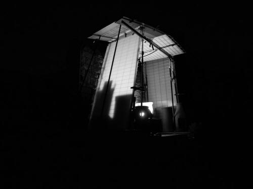
The shelter at night.
To
the right of the shelter, the versatile metal structure, the triangular
supports almost hidden by runner beans, in the distance, the greenhouse main
structure - its triangular structure isn't apparent in this view, but it
would be obvious in a side view, from the west. The trees to the right are
hazel trees, allowed to grow tall this season.
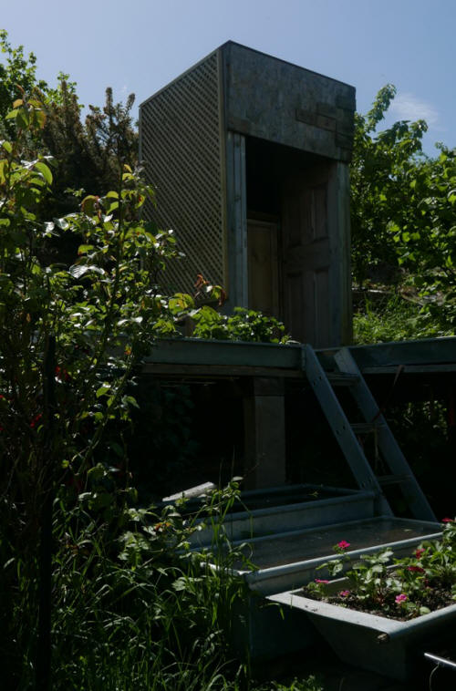
The replacement structures - shelter and propagator
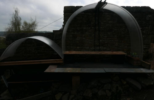
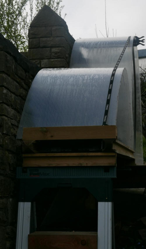
Above, views of the shelter-propagator from the side and the front
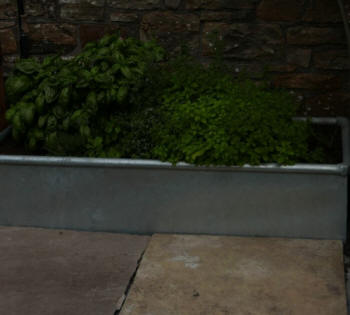
Below, after installation of a galvanized container, used for growing
herbs: basil, oregano, marjoram and thyme. The sheet metal surface of the
platform now has a covering of stone.
These structures are very easy to construct. There are details, not shown in
the image above, which are essential for the stability of the structure,
particularly in strong winds. With these in place, the structure is
rock-solid, despite the use of polycarbonate sheets - their curvature
increases its strength.
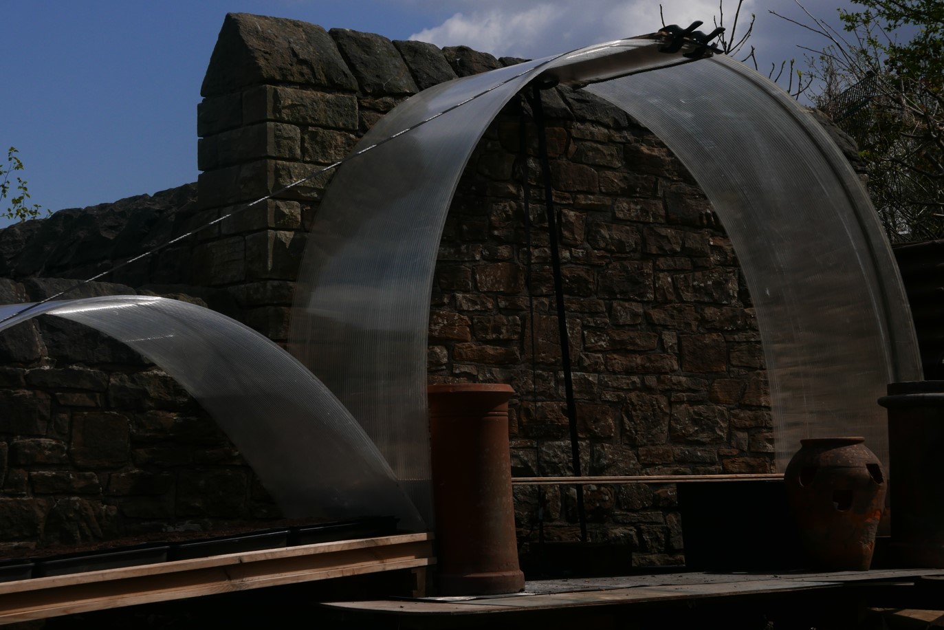
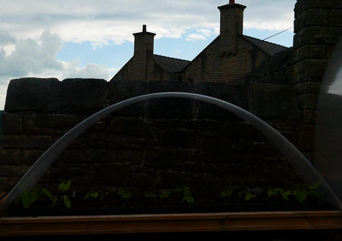
To the left is the smaller curved surface of the propagator roof. A flat
polycarbonate sheet is used in a vertical position to close the one open
side of the propagator compartment. Seed trays containing compost are placed on the wooden boards which
make up the upper floor of the structure, which is retained from the
earlier structure and which can still be used for storing apples and other
things. The wall is West-facing and heat-retaining.
To the right is the larger curved surface of the shelter roof, made up of
two linked polycarbonate sheets. The oak boards supported by the two black
water storage containers are retained from the earlier structure. Also
retained, of course, is the platform which supported the earlier structure,
made of sheet metal. The photograph shows the structures before cleaning
work has been carried out.
Beneath the platform and towards the front of the platform are some of the
rubble stones which are a feature of this part of the allotment. Not shown
in the photograph are the rubble stones which form a rockery, with
ornamental plants. All the stones have been removed from the soil of my two
allotments, except for some Welsh slate (again, rubble stone, not roofing
slate), not visible in the photograph. Geology, including the geology of
this area, is an interest.
This platform, the 'lower platform,' like the 'upper platform' of the next
section, gives a good view of the gardens, not available at ground level.
The small increase in height is significant.
Already, this shelter has had important benefits, particularly when the
Spring weather has been too cold for comfort or too windy for comfort.
Working in poor weather is one thing, resting in these conditions for a time
after working is another.
Below, a very small greenhouse building in the lower allotment, dismantled
now:
The 'upper platform'
This platform is amongst other things a viewing platform, giving a
viewpoint obviously very different from other fixed viewing points. Most of
my time in these allotments is spent working, obviously not all of it. In
rest periods, I prefer to sit in a place with some visual interest, but this
photo isn't about the view from the platform but a view of the platform.
Visible here are the two oak beams supported by four vertical oak beams, the
galvanized water tank which can be used as a subsidiary water source but is
also a container for water with a calm, limpid surface. In the water is a
water lily, variety James Brydon, which produced an abundance of flowers
earlier in the season. It's described by Stefan Buczacki in these
terms, 'deep red-pink, semi-double to double, fragrant, red stamens with
gold tips, dark green to purple, leaves with reddish flecks, justifiably one
of the most famous and popular of all water lilies.' Also visible, at top
left, one of the walls of the narrow shelter.
Since the photograph was taken, this wall has been given more visual
interest by the installation of a large wooden trellis panel. The trellis
wall is visible in this photograph of blossom on one of the cider apple
trees, variety Dabinett:

The shelter contains a cupboard for storage, with more storage space
available on top of the cupboard. A feature of the interior is
the wood, easily visible from the exterior. Interiors seen from exteriors
constitute a field which interests me. Quite ambitious projects would be
possible - wood panelling and other surfaces, in larger spaces furniture
with aesthetic attractions - as well as usefulness.
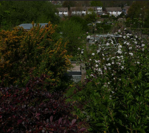
Below, all that can be seen of the platform here is the sheet metal roof
of the shelter, part of the boards and part of the galvanized water
container on the upper part of the shelter - there's a similar water
container on the lower part. More obvious, gorse in flower on the left, the
apple tree 'Spartan' in flower on the right and a row of houses in the
distance.
The
platform has multiple functions. One of these is container growing. Visible are some of the galvanized metal
containers, with lettuces. To the right of the platform, the purple flowers
of purple loosestrife (Lythrum salicaria) and a Bramley apple tree.
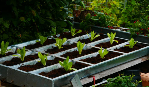
A closer view of the containers, which are sheep troughs, available from
agricultural merchants.
The galvanized container on the platform used as a water container (and a
place for growing a water lily) is one of many water containers I use or
have used. Watering with a watering can is much more convenient than
watering with a hosepipe and I've made sure that no part of any growing area
in the two allotments is far from a water container.
The water containers are of very different sizes and very different kinds.
None of them have a single use, water storage, except for the large water
storage container outside the greenhouse, the agricultural container made of
plastic inside a metal framework, holding 1000 litres (1 tonne) of water.
Apart from this one, all of them provide a habitat for water lilies and
other plants and in some cases for frogs and other animals.
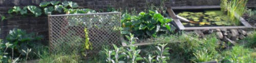
This is a raised pond I constructed for water storage, aquatic plant growing
and a base for frogs, with, to the left, a squash plant growing strongly,
some of its growth against the wall, and a trellis for growing climbing
plants. The pond was dismantled when I constructed the much larger pond at
the bottom of the allotment.
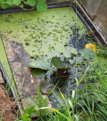
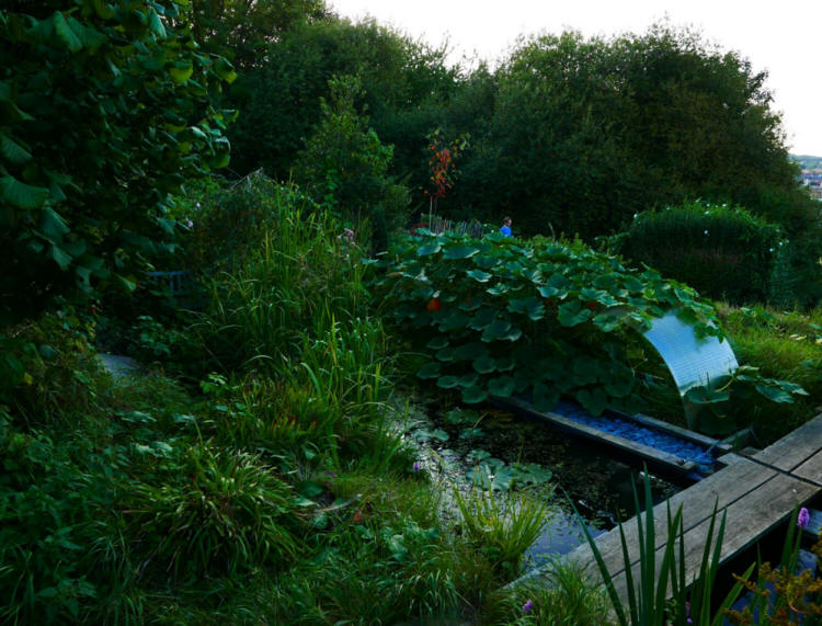
This is the pond inside one of the greenhouse extensions, underneath a
curved polycarbonate roof (which can be used to direct rainwater to the
pond.) I often take water from it with a watering can to water tomato plants
in the greenhouse but it's popular with frogs. On the left, there's the
floating board which makes it easy for them to leave the pond if they so
wish. The pond isn't looking at its best here. It needs some maintenance, of
course, and the water taken out has to be replaced.
The main pond and the structure for
protected growing of squash or other tender plants
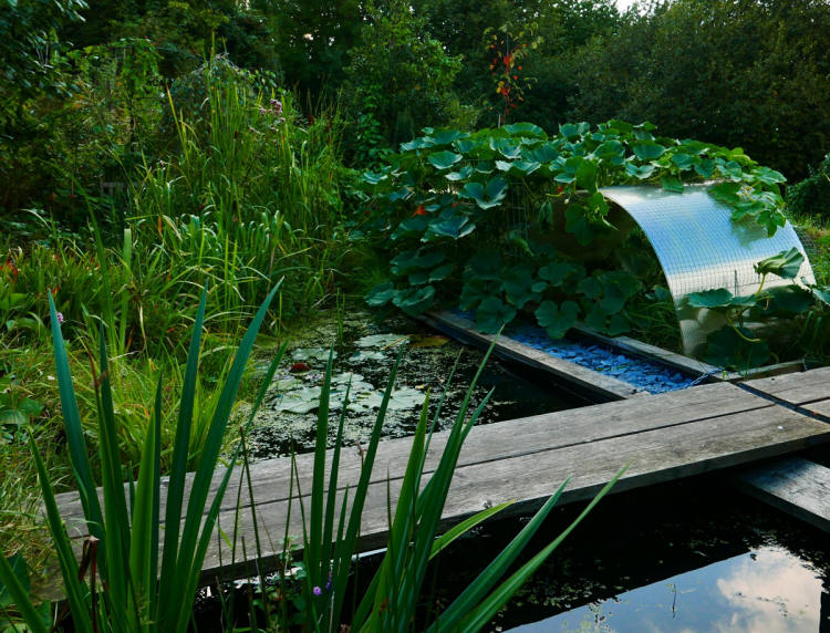
A view of part of the pond. The long wooden path which runs a long
distance from the lower boundary of the allotment, almost, to a higher
point, crosses the pond here. As the 'centres,' or support points for the
boards, are quite far apart, more than the recommended distances, the wooden
boards are strengthened with steel rectangular section, underneath the
boards. The protected cropping, or protected growing of the squash plants is
achieved by two curved polycarbonate sections, only one of them visible
here. There are also galvanized mesh panels to support the squashes (variety
Uchiki kuri.)
Another view of the pond, obviously from a higher point, and of the
surroundings, including the public road. I laid
down aggregate, of Welsh slate, in the band at the North side of the pond,
between the two oak boards. The slate doesn't have the strong blue colour
shown here. I never adjust the colour of photographs even in a case
like this, when colour adjustment would make the colour of the slate more
'natural.' The wooden walkway over the pond gives access to the growing area
at the bottom of the allotment.

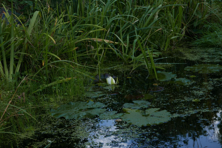
Another view of part of the pond, including a flower and leaves of the
native water lily, Nymphaea alba. Hanging over the leaves of the water lily,
one of the many graceful pendulous sedge plants (Carex pendula).
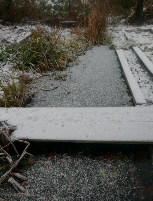
Above, another view of the pond, winter
All the other plants in the pond and near the pond are British
natives, including these: Common bistort (Persicaria bistorta). The leaves are edible and used in
bistort pudding, made particularly in the north Pennines, water violet (Hottonia
polustris), mare's tail (Hippuris vulgaris), scouring rush (Equisetum
hyemale), marsh marigold (Caltha palustris),
water mint (Mentha aquatica), water forget-me-not (Myosotis scorpioides),
great reedmace (Typha latifolia), T. minima, hemp agrimony (Eupatorium
canabinum), meadowsweet (Filipendula ulmaria), water avens (Geum rivale),
marsh cinquefoil (Potentilla palustris).
Below, another view of the British water lily Nymphaea alba in bloom in the pond

Below, marsh marigold (Caltha palustris), foreground, with dandelions,
background. Every year, particularly in one period of concentrated attack,
dandelion seeds are parachuted into this area in immense numbers from
outside the area. To watch them slowly descend is to realize the difficulty
of controlling them, the futility of trying to control them, even. I dig up
dandelions when they are obviously going to interfere with a particular
plant I want to encourage. In some cases, the dandelions can be made to fit
into the area by blending them with other yellow flowered plants, such as
the marsh marigold here.

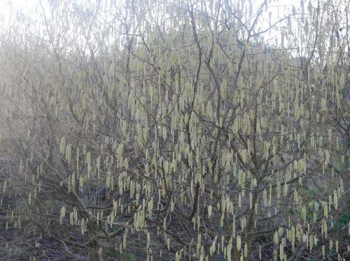
Below, views of some of the Hazel trees in the double row leading down to
the pond. The water-collecting surface shown below is in the space between
the rows. There are six trees in these two rows and two more Hazel trees
higher up the allotment. The trees are various varieties of Corylus avellana
and Corylus maxima. The trees are shown in winter, with catkins, the male
flowers. The trees are wind-pollinated. After being pollinated, the female
flowers go on to produce the fruit, the cultivated hazel nuts.
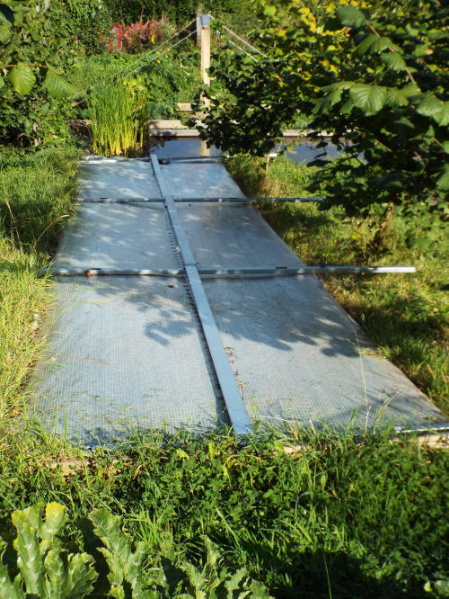
Above, view to the South: the water collecting surface which directs water to the pond or
the bog garden in
rainy weather and reduces the need to use tap water. The surface is fixed
firmly in place and is unaffected by high winds. Between the pond and the
near edge of the water collecting surface is an area of bog garden, not
shown in the photograph above. It was taken before the establishment of the
bog garden. Water from the plastic sheet now goes into the bog garden, but
an extension can be added to the plastic sheet so that the water from the
water collecting surface goes into the pond itself.
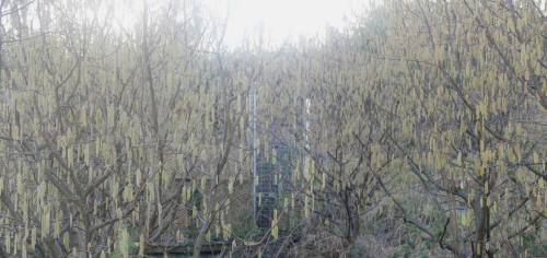
Above, view to the North, showing the water-collecting surface in its
setting, a double row of hazel nut trees. THere are six trees here (and
others higher up the slope.) The trees are much larger now and cast a dense
shade, For most of the time, the plastic surface isn't in place and I've
allowed the plants that grow in the area between the hazel nut trees to grow
without much intervention - apart from the planting of bluebells. The
hazelnut trees do need intervention - they now need drastic pruning.
The water collecting surface can be used for plant propagation and for growing plants in
containers, whilst continuing to collect water and take it to the pond.
The containers are placed on structures which are supported by the aluminium
bars shown in the photograph.
Alternatively, the water collecting surface can be put in place in rainy
weather and removed in dry weather, to allow the vegetation in the area to
grow naturally. When the plastic sheeting is in place, then the plants will
still grow, of course, but in a form of 'protective growing,' the air
temperature raised by the plastic sheet.
This waterlily - the native waterlily Nymphaea alba - has continued to bloom
well into November, but the weather hasn't co-operated and the flower hasn't
opened to reveal the golden core hidden here by white petals.
A view of the squashes in late October from another direction, from the
road, with a background of grape vine and hop plant growing against the
stone wall.
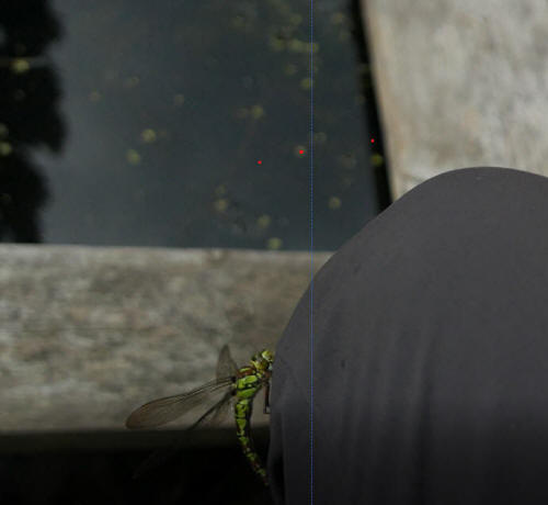
A welcome visitor, a dragonfly (Aeshna
cyanea.) A dragonfly of this species has visited the pond every year since i
constructed it and they aren't at all wary of people - quite the opposite.
I've so often seen them but never actually seen them hunting anything, let
alone killing and eating the prey.
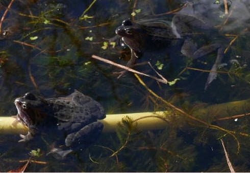
Welcome visitors / residents: frogs (Rana
temporaria) resting.
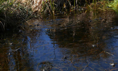
Adult frogs come to the pond in spring to mate in large numbers. The
photo here shows some disturbance of the water but not the commotion of
their mass frolicking, which is accompanied by sustained and surprisingly
loud booming sounds. Later, after they hatch, the density of tadpoles in the
water gives me cause to think gloomy thoughts, about the waste of nature,
the fact that of the very large number of tadpoles I see swimming, only a
very small proportion will survive to adulthood.
The area immediately above the main pond: beans, hops, grapevine, hemp
agrimony and meadowsweet
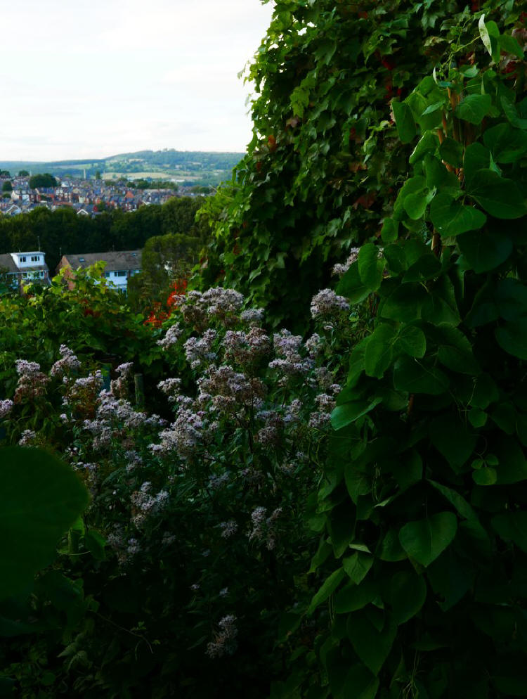
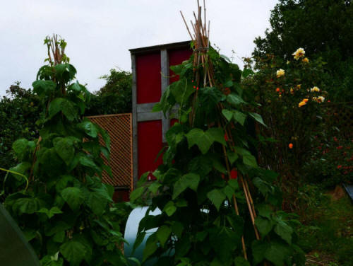
In the distance, low hills and Sheffield houses. In the foreground, runner
beans (variety 'Lady Di') growing up cane pyramids, In the foreground, Vitis
vinifera 'Brandt,' which has made full use of the strong supports I made for
it against the stone wall, and on the left, hemp agrimony (Eupatorium
cannabinum.)
In front of the triangular support structure, a
runner bean pyramid, hemp agrimony to its left, and to the right, hazel nut
trees. In the lower right hand corner, a flower of Persicaria bistorta.
Upper allotment growing area and storage
area
Above, two French bean pyramids (variety 'Cobra') growing up cane pyramids,
partially hiding the curved sheet metal wall / roof of the pizza oven I
constructed, with, beyond, the small building which was one of the first
that I constructed in the allotments. Right, a very fragrant rose, variety
Arthur Bell.
Above, the same elements as in the previous photograph,
with the addition of sections of my vine trellising system used to grow the
red grape vine variety 'Regent,' and the water-collecting path, described in
the first section of the third column of the page - a long ladder as the
foundation, short boards forming a surface which can be walked on, covered
by the impermeable black surface sheets (easily detachable) which direct
water to a galvanized storage container at the base. The entrance to the
greenhouse is very near to the container and using a watering can to
transfer water from the storage container to the plants growing in the
greenhouse is the quickest and most convenient method of watering. There's a
much larger water storage container in this area, one of the agricultural
storage containers often seen, a plastic container holding 1 tonne of water
inside a metal framework for support. This has to be filled with a hosepipe
from a mains tap not far away.
The
trellising system for support of grape vines is intended to eliminate some
disadvantages of the post and wire system, by far the most widely used
system of support. It eliminates the work of anchoring the post in the soil
and it eliminates the inconvenience and worse of working with wire.
Instead,
I make use of lightweight metal sections which are easily slotted together,
kept in place with ground anchors or simply metal pegs - which, after all,
are capable of keeping tents in place even in very strong winds. The system
also makes possible the use of plastic sheets for harvesting of grapes
under cover, and a method of transporting the harvested grapes the length of
the structure, within the structure. Of course, commercial implementations of
this system would be much longer than the short section here.

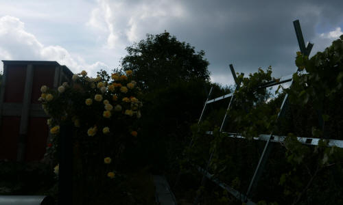
Above, part of the vine trellising system and the
rose Arthur Bell, downhill view, from the North. In the previous image, the
view was uphill, from the South. The golden yellow of the flowers fades and
the flowers become creamy and then white. Sometimes I remove the paler
flowers and sometimes I let them remain, removing the flowers later, when they are shrivelled.
Below, a much larger structure, made with similar
lightweight metal components, but wider, and with many uses, including
support of netting for plant protection:
Below, traditional honeysuckle, in direct
sunlight and light shade, the upper boundary of the upper allotment:

Below, the main path of the upper allotment,
before installation of the water-collecting surface:
Other areas
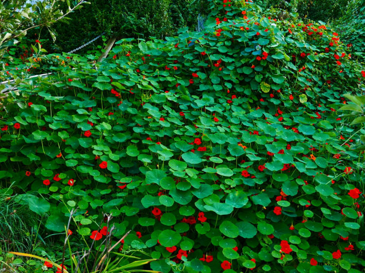
Nasturtium plants (Tropaeolum majus.) The plants
are growing on an earthwork I constructed, to the left, over a privet hedge,
which forms part of the boundary of the upper part of the lower allotment,
which would take a great deal of work to convert from unsightly to slightly
attractive, and, lower down, to the right the semi-composting system which
I've been adding to and using for years. This is a minimum-work system which
has produced good compost. The bindweed which would be growing rampantly on
the privet hedge if the Nasturtium plants weren't here is nowhere to be
seen. The Nasturtium has been steadily advancing to the right (and the other
directions) and is beginning to smother the bindweed which has assumed right
of way. Nasturtium has the advantage of being edible. Nasturtium is a plant
I encourage.
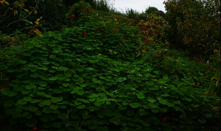
The same bank in autumn. Photograph taken 14
November, 2021.
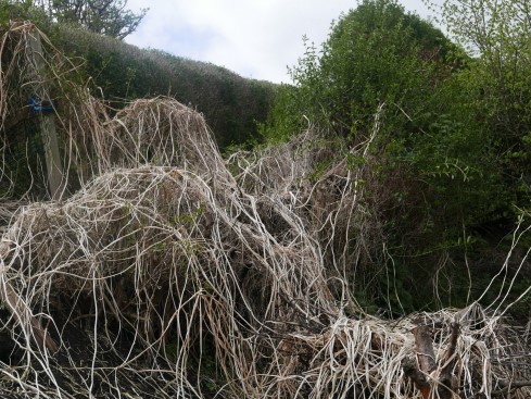
When the plants die, the long dead stems remain
until the next year, when new plants grow. The dead stems act as a mulch,
suppressing weeds.
Below, Hemerocallis growing at the base of the
Nasturtium bank. Photograph taken summer, 2022.

Below, another view of Hemerocallis:

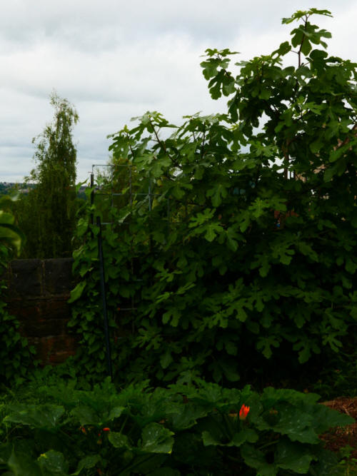
Growing against the low wall, a fig tree,
variety 'Brown Turkey.'

Growing near to the fig tree, by the same low
wall, Lavatera.
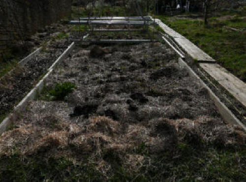
Above, a thick application of manure and straw to a
bed between the wall, left and the wooden path, right.
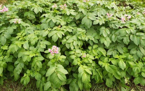
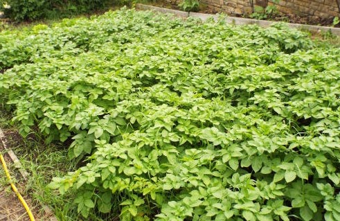
Above, two views of the same bed, showing
potatoes in full growth, the variety 'Kestrel,' with pink flowers.
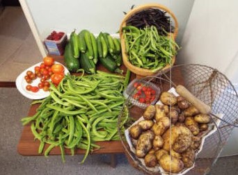
I hardly ever take photographs of the produce
after harvesting.These are exceptions. I'm self-sufficient to a very large
extent in fruit and vegetables.
An allotment next to a road has advantages and
disadvantages. This area in the lower allotment is useful as a delivery area
for manure, which can be tipped from a tractor equipped with a front bucket.
I use another place here for delivering bulky materials. Some of the manure
will be used for suppressing weeds, such as the nettles visible at top left.
A general vew of part of my lower allotment
(and, to the right, a neighbouring allotment) seen from the busy public
road. In the foreground, two small Yew trees can be seen, in my allotment.
To the right, there's a tall Lombardy cypress hiding another cypress, in the
neighbouring allotment.
General comments
I did very little work at the allotment from late
autumn of last year (2021) through the winter and into the spring of 2022. I pruned the
apple trees quickly. The plum trees and fig trees received no pruning at
all.
I was committed to a practical objective which I found absorbing but
which hadn't been solved - designing hydraulic machinery for log splitting
as well as apple pressing which was easy to assemble and easy to dismantle.
Designing these machines wasn't at all easy. I designed and constructed a
machine which paid attention to ergonomics, so that the different operations
- pressing the apples is only the last of these - could be carried out at
the one 'workstation.' The machine was successfully used for apple
pressing but it was obvious that it couldn't be used for log splitting.
Commercially available machines are designed and used for one purpose or the
other, not both. I wanted a versatile machine which could handle both.
I
eventually came up with a very different machine, which made extensive use
of threaded rods and perforated steel bars, the lower steel bars concealed
by wooden components, as well as ratchet straps, used in tension, not
compression, of course. The use of ratchet straps eliminates the need for
some strong metal or wooden components - so far as I know, a unique
feature for this kind of machine. The machine is tall. It includes supports
for roofing panels. I've used polycarbonate sheets as the roofing panels.
The machine is indoors, without the panels, but if the machine is used
outside, then construction of a small building to protect the machine
against the weather and to provide shelter for the wood splitting or apple
pressing operations would be simple enough.
The most difficult part, one
which took me a long time to solve, was designing and constructing the
multiple cutting head, using various items available to me. This machine can
be used for log splitting and apple pressing. It has only been tested on
logs but log splitting is a far more severe test of a hydraulic machine than
apple pressing, so I can be sure it will succeed with crushing apples. I
installed supports for another hydraulic machine, a very simple but strong
hydraulic machine, in the lower allotment, for use with a ratchet strap with
a rating of 10 tonne, the hooks of the ratchet strap attached to ground
anchors in concrete. This is intended to be the only machine for apple
pressing - it's near to the apple trees - whilst the machine which uses
steel threaded rods will be kept in the house and used for log splitting.
The solid fuel and wood burning stove is very near to the machine.
There have been radical changes to the rectangular
greenhouse extension, the one with a wall made up of straw bales. Years ago,
when I constructed the extension, I chose to construct a flat roof, made up
of OSB3 boards covered with sheet metal. After a long and exhausting day, I
drilled holes into the sheet metal and installed screws (self-drllling
wingtip screws.) Although the screws were 'self-drilling' it was easier to
drill preliminary holes. I didn't fix in place all the screws I intended to
place. If I'd continued working, I felt that there was a danger of an
accident. I'm used to working at a height but it would have been stupid to
continue under the circumstances. Not long after, before I was able to make
the roof fully secure, there was very bad weather - very strong winds, which
damaged the roof severely.
I didn't repair the roof. I had the instinctive
feeling that the design of the roof could be improved. I could do much
better, but I had no ideas which could lead to an improved roof, not just an
improved roof but one which didn't depend on conventional roofing methods.
This year, I did solve the problem, with new and
radical method which will need to be explained much more fully than I can at
the moment. Installing the new roofing was very easy and very much safer
than the previous method, or, I think, any conventional method. It makes
very easy the implementation of slope, essential, of course, for the
draining of water from the roof.
There are various components. The main one is
corrugated clear (or opaque) plastic sheeting, easy available, which is
sloping. In conventional systems, the roof is higher than the walls and
implemtation of sloping for a roof isn't an easy matter. In this design, the
roof is lower - slightly lower - than the walls. In this position, the roof
is protected from strong winds by the walls. The roof is sheltered rather
than exposed. Plasterboard or another suitable material can be installed
below the corrugated sheet so that it can't be seen, but in this garden
building, I've allowed the corrugated sheet to be visible. The sheet extends
the full length of the building and protrudes from the wall at the front.
This can easily be seen in some of the images. The plastic sheet is a
water-collecting surface. Rain water is directed to the lower end
(obviously) and then makes a small waterfall, being collected below, in a
container at ground level.
Above the corrugated plastic sheet are wire mesh
panels, which also run the full length of the building extension. These are
used to provide attachments and support for plants, if the roof is intended
to be a 'green roof.' The roof here supports the upper growth of a hop
plant, variety Target hop, as well as the upper growth of a grape vine,
variety Regent, a red grape variety. Hops and grapes can be harvested from
the roof as well as the lower growth on the walls - a ladder allows easy
access. The wire mesh also prevents leaves, or most leaves, from falling on
to the plastic sheet, important particularly in autumn at the time of leaf
fall.
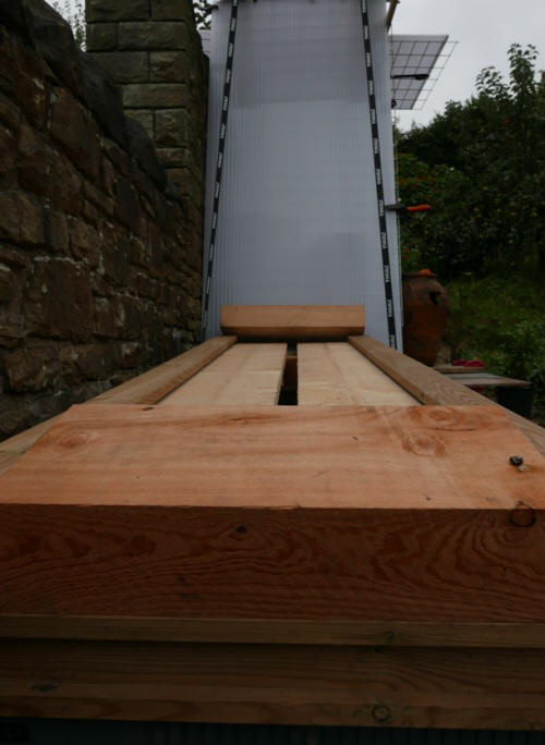
I've designed and constructed an addition to the roof
rack of my van. The design, which utilizes wood and ratchet straps, is quite
intricate. I've made the utmost attempt to make the system as strong and
safe as possible. Roof racks have the potential to be very dangerous. It's
very difficult to prevent some materials from sliding. This system allows me
to transport materials such as long lengths of timber and bulky sheet
materials, sheet metal or plastic or wood, which are too large to fit in the
interior of the van.
Ridges in the sides of the long wooden components -
they're 2.7m long - allow the insertion of the upper ends of polycarbonate
sheets. Four of these sheets, with their upper ends inserted into the space,
can be bent to form curving sides, with their lower ends kept in place at
ground level by a variety of methods. I've also designed supports for
straight polycarbonate sheets at the rear of the van.
This design is much quicker to erect than my existing
design, described, with images, on
my
main page on PHD Design.
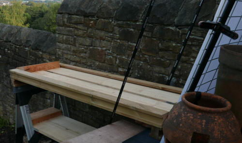
I designed a workbench constructed from oak with a
thick beech top, one which for all its size and solidity is very easy to
install and very easy to dismantle. It's described on another page. I've now
designed and constructed a less elaborate workbench with a long sheet metal
work surface for outdoor use. Outdoor working has advantages for both
woodworking and metalworking if the weather is suitable. For example,
hazardous dust produced by the sawing or routing of oak and other materials
is less hazardous in the open air. My workshop is cramped. It has to be used
for the storage of timber and metal, such as long steel hollow section,
storage of hand tools and power tools, storage of many other things. The
space is used effectively, I'm sure, but there isn't enough space.
An outdoor roof which is level, not inclined, should
be avoided, as there's the problem of shedding water. A sloping roof is far
preferable. For this reason, the working surface of the workbench slopes! A
sloping workbench is perfectly usable for many or most operations. In some
ways, there are advantages as compared with the usual horizontal surface.
At the bottom of the lower allotment is a small
structure made up of two curved polycarbonate sheets which has been used for
storing sraw bales under cover. I've made use of the straw bales and now the
double structure is used for growing squash plants. I added steel mesh
sections which give vertical and horizontal support to the plants. The
squash has covered a large part of the area available, despite the poor
growing conditions this year for squash and other plants which thrive in
higher temperatures (the tomatoes in the greenhouse have grown well but
there haven't been nearly enough ripe tomatoes. I'm not surprised.
Making a path
Converting a manual apple press
into a hydraulic apple press
PHD workbench
PHD
low-level sheet metal workbench
Another
sheet metal workbench
Safety
in sheet metal work
The
workshop
PHD
solar wood store
A non-solar outdoor wood store
PHD
A-frame indoor wood store and crane
A
chainsaw stand
Steam
bending of wood
PHD
outdoor oven
PHD swift nesting box
I give detailed information about my original
design for a swift nesting box and about a much more recent design.
One of the new designs has an open back,
which would allow people inside the room to view events inside the box,
installed outside the window - entry and exit of swifts, nest-building, egg
laying, hatching, feeding the young. I've constructed two different
versions, both of oak and the boxes are also available in larch.
Currently available swift nesting boxes
require working on a ladder at a height. More elaborate equipment is needed
to install the more elaborate swift nesting boxes, which are installed in
substantial groups. I designed a swift nesting box
which is very different from established designs. Below this image, a link to a video (length:1 minute: 24
seconds) showing how easy it is
to install the swift nesting box and how little time it takes.
The swift nesting box takes about an hour to
construct, using only a few commonly available tools. It can be installed in
less than a minute. A link to a very short video showing installation of the swift
nesting box, beginning at 50 seconds into the video. (Before, that, there's
installation of a protective polycarbonate sheet to the lower part of the
window. Not shown in the video, attachment of the upper polycarbonate sheet with two
clamps. The upper sheet is shown in the image above.)
Click on the highlighted text to see the video:
swift nesting box installation
The video first gives a view of the scene. For a
short time, nothing happens, then the simple installation of the nesting box
is shown. From the video (1 minute, 01 seconds): moving the
nesting box from inside the room to outside the window. The nesting box is
then secured. This is a 'basic installation.' I devised additional security
features to ensure that the box will never fall.
I've already installed a polycarbonate sheet on the
lower part of the window. After the nesting box was secured, I installed a
smaller polycarbonate sheet on the upper part of the window.
Polycarbonate sheets act as anti-reflective surfaces. Glass windows
are very reflective and when the reflected image is an image of the sky,
swifts (and other birds) can fly into the glass and be injured or killed.
There are many anti-reflective coatings available for glass which prevent
harm to birds and which have minimal effects on light transmission but
polycarbonate has the advantage that it provides a much softer surface if a
bird ever did collide with it.
This new design is a swift nesting box which
is installed outside a window but from within the house, without the
need to climb a ladder and work at a height to drill holes in masonry, to attach a nesting box to its
support. From the site of the Health and Safety Executive,
https://www.hse.gov.uk/toolbox/height.htm
Working at a height remains one of the biggest
causes of fatalities and major injuries ... avoid working at height where it
is reasonably practical to do so.'
Interlude: an appreciation.
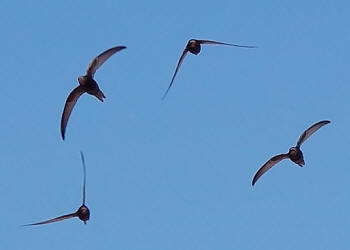
I live in an area of Sheffield where swifts used to
be plentiful. In the last two seasons, numbers have dropped
alarmingly. My own small terraced house doesn't offer any
entrance holes for swifts. I designed this nesting box to make it much
easier to help these wonderful visitors to maintain their numbers, to
increase their numbers - and to continue to bring to people like me
inexhaustible joy when we watch their soaring and swooping and turning and
when we listen to their cries in the summer sky.
I don't live in an idyllic village but in a suburb of
Sheffield, not far from the Hillsborough football stadium. Swifts are birds
of town and city suburbs rather than villages. If, hypothetically, I
were offered the chance to live in a beautiful and idyllic village without
swifts rather than here, I wouldn't. I'd rather live in an ordinary
suburb with swifts than a beautiful and idyllic village without swifts.
Without the sight of the swifts, the summer skies would seem empty. Without
the sound of the swifts, the summer skies would seem silent. But the summer
skies last year were silent for very long periods. In the swift season,
there were far fewer swifts than there used to be, and the trend began some
years ago.
I own a very good ladder, tall enough to reach the
upper wall of the house and I'm used to working at a height, but I wanted to
design a swift nesting box which doesn't require a ladder or the confidence
to work at a height. Installing a box of standard design isn't a job to be
undertaken lightly, but I support completely people and organizations
installing swift boxes of standard design - the standard design has many
variations, of course - when, as will almost always be the case, safe
working is practised.
This new design offers the advantage of easy
construction and ease of installation. Some other advantages of
the design: The box can be checked for unwanted users, such as starlings
and other birds using the Swift Box instead of swifts. If birds other than
swifts are seen entering the swift box, then the box can easily be taken
into the room temporarily for a check. If any eggs laid by
intruders are found, the eggs can then be removed. Swift boxes are for
swifts, and only for swifts. Starlings and birds other than swifts which lay
their eggs in swift boxes are much more common than swifts. For example, the
breeding population of Sturnus vulgaris, the starling, is about 1.8 million.
This is what the eggs of the swift Apus apus look
like:
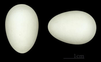
Checking the eggs is one
operation which this swift nesting box makes easy. At the end of the
season, when the box is taken down, the interior can be cleaned. This is
another operation which this swift nesting box makes easy.
A short section of contrasting, supplementary information before I
return to the swift nesting box, including this: how I store my longest ladder, the one I
would have used if I'd installed a swift nesting box high up, at roof level.
I haven't seen swifts in the skies above my
allotments very often - when I have, the sight has always been thrilling,
momentous, in fact. It's cause for regret that the school buildings next to
the allotments aren't used by swifts for nesting.
This is a design which fits this particular window.
The box is supported by fabric straps with additional light security chain
(information about the chain not provided in this introductory material.)
If,
hypothetically,
the straps failed (but I've good reason to believe this is a very remote
possibility) the chains would ensure that the box couldn't possibly
fall to the ground. This would benefit any swifts inside the box, of course,
as well as anyone below the box.
I
use fabric of various dimensions and with various maximum loads in a variety
of designs, including the use of ratchet straps with a rating of 10 tonne in
my apple pressing and log splitting hydraulic machines. Fabric can be
immensely strong. Modifications to the design - again, no further
information provided here - allow for the installation of the nesting box in
windows of widely different kinds, with varying methods of opening.
The danger of swifts (or other birds) colliding with the
window is avoided by the use of polycarbonate sheets, installed at the same
time as the box. There are many other anti-reflective techniques which can
be used to avoid the danger of collisions with windows. The polycarbonate
sheets also protect the window from any slight movement of the box in strong
winds. The box has been tested in strong winds. The dimensions of the
polycarbonate sheets obviously differ when windows of different sizes are
used for placing the nesting box.
The material in this section is wide-ranging. It
includes the practicalities of constructing a swift nesting box and my
gratitude for the exhilarating, deeply satisfying, experience of watching,
and hearing, these magnificent birds.
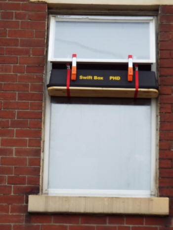
The swift box is lower than it would be if it were fixed
below the gutter of the house, and not slightly lower, but the height is
just about adequate.
The entrance holes are a little more than 5 metres
above the ground, the recommended minimum height for installation of swift
nesting boxes - although swifts have nested in boxes much lower. In houses where the upper room is higher than in this house, the height
above the ground would be more than adequate.
Instead of climbing a ladder and working at a height to
attach a nesting box underneath the gutter, I open the window wide,
attach two light clamps to the window frame, pass the swift box from the
room to the outside, and, holding the box in one hand (the box is light),
use the other hand to push the fixings attached to the red webbing straps
(steel snap hooks)
onto the handles which open the upper part of the window. The box is held securely in place.
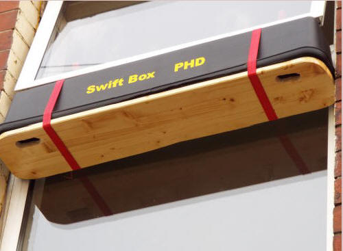
Below, the swift nesting box on the workbench in my
workshop. A workshop isn't necessary to construct the nesting box in the
least. It consists of a black plastic upper part and a wooden base. The
two components are fastened together with the two red webbing straps. The
base can be easily removed. The view below is of the edge of the base. The
flat lower side can easily be seen in the video above, with the two entrance
and exit holes for the swifts.
In the image below, the metalworking vice at the right and the pillar drill at the
back aren't needed. The upper part of the swift nesting box needs no construction at
all all - it's simply a black plastic planter, easily obtained. The wooden
base, seen edge on here and secured with the two red straps, is the same
width as the planter. It simply needs sawing to length with the handsaw (or,
of course, a power saw). The board can be secured to a table or bench with
two clamps, one of them shown here. After that, the corners are rounded with
the craft knife.
To form two entrance holes for the swifts towards the ends
of the wooden base, two holes are drilled close together using the portable
power drill (or a hand drill) and the circular holes are formed into two
oblong holes using the craft knife.
On top of the nesting box, secured by
the red straps, are two metal snap hooks. These simply fit over the handles
used to open the upper part of the window and the nesting box is dropped
into place. Thin, unobtrusive chains attached to the handles supplement the
straps. With the straps and chains in place, the box is secure and can't
fall.
The actual procedure is marginally more involved than
this but perfectly simple and straightforward. After opening the window, I
pass through the window opening a sheet of twin-wall polycarbonate and use
two clamps to hold the polycarbonate sheet in place. The fixings are
then pushed onto the handles of the clamps. Then I pass through the window
opening a second, smaller piece of polycarbonate sheeting, securing it with
a second pair of clamps, the prominent red, white and orange clamps in the
photo above (the lower parts of the first set of clamps are also visible.)
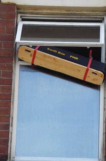
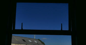
Below, a view from within the room before attachment
of the swift nesting box - the two handles used to open the upper part of
the window are raised. The window is opened, the box is moved outside the
window and the two metal snap hooks on top of the swift box are lowered into
place, fitting round the two handles. Clamps are added, together with chains
are added for additional security.
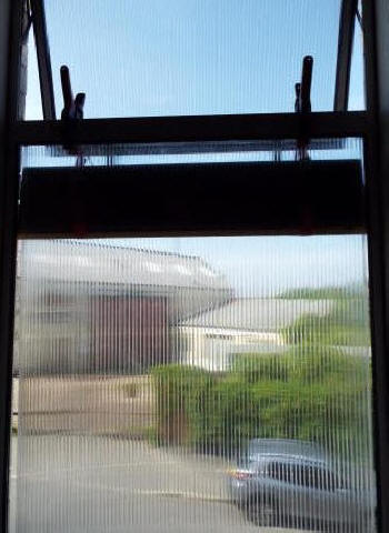
Below, another view from within the room - the
nesting box just outside the window, held in place by two of the clamps,
which also support one of the polycarbonate sheets. The polycarbonate sheet
for the upper part of the window isn't shown here. It's secured by two more
clamps. Beyond, a view of the
motor body repair shop across the road, now closed. I could achieve a clear view of the
motor body repair shop by using a different method of protecting swifts and
other birds from colliding with the window. I prefer to use these
polycarbonate sheets. They can obviously be removed at the end of the swift
season.
The polycarbonate sheets are to protect swifts (and
other birds) from injury or worse by collision with the glass of the window.
Polycarbonate is a much softer and more yielding surface than glass and
polycarbonate, unlike glass, doesn't give reflections or the illusion that a
free flight path is available to the bird through the window. Polycarbonate
has high light transmission and inside the building, there's still a view to
be had, although obviously a more diffuse one. There are various other
methods of protecting birds which don't involve the use of these sheets.
Further information about construction. The box
consists of a plastic planter, black in this case, available from suppliers
of gardening equipment, together with a base, made of timber board in this
case. I did varnish the base, which obviously adds to the construction time,
but this isn't essential. Planters come in a variety of sizes, including
ones suitable for smaller, single nest boxes. The planter here has a width
of 20cm and the timberboard as bought has a width of 20 cm. All that has to
be done is to saw it to the right length - a metre, in this case. Plastic
protectors can be added to the corners of the base, but I used a jigsaw to
round off the corners. A jigsaw isn't an essential tool, though - a rounded
corner can be approximated by making cuts at the corner with a saw.
The only tools which are essential to construct the
nesting box are these:
A saw (handsaw or power saw) to cut the wooden base
to length and to cut the corners of the base if a jigsaw isn't used. (The
base may also need to be cut to width.) I used a handsaw.
A drill, mains or battery-powered - or a hand drill -
to make two holes close together in the base for each entrance hole. The
space between the two holes is then cut away. This is very easily done.
I used a battery-powered saw. A suitable drill bit is quite substantial but
not expensive. The diameter needed is 28 mm. I used a 28 mm auger drill bit
of length 210 mm. The point of the auger drill bit allows the centre of each
circle to be placed precisely.
A chisel or knife - I used a craft knife - is used to
trim away excess wood, in this diagram the light area between the two shaded
circular holes. This gives an entrance hole of the right shape and a
suitable size, in this case 28 mm x 65 mm.

The plastic compartment is held to the base by two
narrow webbing straps which can be put into place in very little time.
In the top photograph above and in the two videos, these straps, narrow and
red in colour, are easily visible. These webbing straps are very strong. I
use webbing straps (of greater width) in the design of hydraulic equipment,
for bending sheet metal and pressing apples to produce apple juice.
Obviously, taking the nesting box back into the room
and dismantling it, perhaps for cleaning at the end of the season, is a very
quick and easy matter too.
Installing (and removing) this nesting box is a much
less hazardous activity than installing or removing an external nesting box
of the usual kind, one which is higher, perhaps beneath a gutter, working on
a ladder, but there are possible hazards to passers by. These hazards are
easily avoided. Two people are needed to place or remove this nesting box,
one inside the room, at the window, and one at street level, who can warn
the person inside the room if people are approaching and who can request
that they keep away from the area underneath the window. This is a light
piece of equipment, not at a great height, but obviously, hitting a passer
by has to be avoided - made impossible.
The common - most common - design of swift nesting
box, installed under the gutter, is kept in place by fixings which can fail.
Boxes of this design are in place for years, exposed to the weather, and
parts of the box and its supports can fail. Visual checks on the box should
be carried out from time to time - binoculars can give a better view, of
course - and every so often, when possible, a safety check from the top of a
ladder is advisable.
A falling nesting box would
probably harm any swifts inside at the time - this too has to be avoided -
made impossible. The clamps and webbing straps are so strong that the
possibility of their failing can be discounted and in any case, if one clamp
or strap did fail, the box can be held in place by the other clamp and
strap. The box is unaffected by strong winds but hasn't been tested in
gale-force winds, of the kind which cause widespread damage. I've good
reason to believe that it would withstand these winds.
It's very unlikely that the nesting box will be used
by any swifts in the area for bringing up young this season, and probably for
several seasons or many seasons. More often than not, this is the case with any nesting box
installed in or outside a house. The chances of success are increased by
playing a CD of swift calls. The open window (only slightly open) would
allow the sound to reach the surroundings easily but so far, I haven't
played a 'Symphony of Swifts' CD.
The new design
Now, I've worked on a new design and constructed two nesting boxes of the
design. They are much heavier than the earlier box.
Both boxes are open at the back, which presses against the window when
the boxes have been installed. This allows a view into each box, so that if,
with luck, swifts use the box, events can be observed from inside the room:
entry and exit of swifts, nest-building, egg laying, hatching, feeding the
young.There are
problems to do with possible disturbance but I think that the problems can
be solved. A solid back can be inserted, to give a box of established
design.
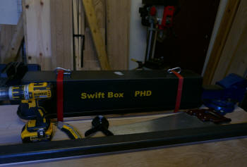
The heavier swift box in the foreground is higher and wider than the box in the
background but not as long. Screws are used in the construction of the box
in the foreground. The orange and red tapes give additional security,
holding the box together even if some of the screws were to fail. There are
independent systems for securing the box to the supports inside the room.
These supports aren't shown here. The main system relies upon the chains
shown here.
The box in the background is shown with the oen back of the box facing
forwards, so that the inside of the box can be glimpsed. This uses screws
too but the security tapes aren't shown here. This box has substantial metal
brackets in place, which can be used to hang the box over a window fitting.
This is a twin box, able to accommodate two sets of parents and their young.
A partition is inserted into the box to separate the two families.
Below, the wider double nesting box installed successfully on the window for a short time, without the
tapes which give added security to the structure. The box was tried out
before it was quite finished. The entrance holes had not yet been cut in the
base.

Below, two views of the single nesting box, installed for the season. I attached
metal brackets, which fit over a window frame but the box is also secured by
a system of chains attached to two separate anchorages, with strong cam
buckle tapes providing yet another layer of safety.


Below, the nesting box isn't varnished or treated in any other way
but the oak from which it's constructed resists water well. However, the box
is protected from rain and other precipitation in a very simple way, simply
by opening the upper part of the window. The water runs down the sloping
pane of glass and falls to the ground without contacting the swift box.
Perhaps potential users of the system would resist this method or
would have windows which can't be used to protect the box in this way, but
I'm happy to keep the window open for long periods. I've an alternative
covering for weather protection of the roof, very light. very cheap and
simple to install, but simply opening the window suits me.
The box has the
advantage over other wooden boxes in that it can be removed at the end of
the swift season, an operation which only takes a minute or two, until the
time comes later in the year when it can be used as a roosting box. Almost
certainly, it will be used somewhere else for this purpose, most obviously
in a garden or back yard.


Below, view into the box from inside the room, the open side resting
against the window. As is intended, the interior is dark but has been made
lighter for the purpose of display here.

A notable feature of both boxes is that when the swift season is over,
the boxes can be used for a different purpose, as a roosting box. When
winter comes, birds can shelter in the boxes, which are well insulated,
protecting the birds from hypothermia. Structures taking the form of rods
for perching are inserted into the boxes. The holes which are of a size
suitable for swifts can be replaced with other inserts with different sized
holes, suitable for a range of birds, allowing some species to enter but
keeping out others.
This is a flexible and versatile design, then, capable of helping a
variety of birds.
Very much recommended, established Websites
and blogs concerned with swifts, including their material on internal and
external nest boxes, as well as other material to do with swifts.
The members of the Sheffield Swift Network are
doing very impressive work
https://sheffieldswiftnetwork.org/sheffield-local-swift-groups/
Amongst the groups listed on the site is S6 swifts,
the postcode area where I live:
https://s6swiftssheffield.org/
From the S6 Swifts site:
Our thinking was that plenty of people are interested in wildlife, but
that the long ladders and head for heights required to fit swift boxes up
under eaves puts even the keenest people off, or at least means that fitting
a nest box ends up sitting on a to do list for years.
We’re so proud of our local swift colonies and want to do something
to help these amazing birds before they decline further
Lots of people don’t really notice our wonderful, joyful, screeching,
soaring swifts. Many people don’t know the difference between a swift and a
swallow. We want people to feel proud of “our swifts” and that, seemingly
against all the odds, they choose to keep returning to our small corner of
Sheffield each year. To soar and scream over the terraces of Hillsborough,
to squeeze unnoticed under a wonky roof tile in Walkley.
I think that people in Sheffield S6 who want to help swifts would be well
advised to make use of their advice service, which is imbued with a passion for
helping the swifts but takes full account of practicalities, such as the
inconvenience and hazards of working at a height.
Their are other considerations, too, which the S6 swift group obviously take
into account. If a wooden swift box is chosen, and there are good
reasons for choosing a wooden box, I regard it as important that the box
should be very well made. The Website of 'Peak Boxes,' makers of a wide
range of bird boxes, including swift boxes
https://peakboxes.co.uk/
includes this, 'Bird boxes built with thought, care and craft. Superbly
built, specialist boxes for birds, craftsman-made, in the heart of the Peak
District.'
To mention just some of their work, the images on the page
https://peakboxes.co.uk/contact-1
show impressive design and craftsmanship.
It's not always possible to choose something made by a craftsman rather than
a mass-manufactured article and sometimes a mass-manufactured article is the
best choice, but craftsmanship and support for craftsmanship are very
important and in the case of wooden bird boxes, my own view is that a
product of craftsmanship is the one to buy, unless finances make that
difficult or impossible.
For the time being, the
people at S6 Swifts are taking a break - definitely a well-earned break - from their full
service. In this field, as in so many others, it's impossible for people to
give their full attention to a cause, to spend every waking moment on the
cause. There are responsibilities, demands on time and money, pressures -
and other interests as well as legitimate pleasures - which obviously make
full-time preoccupation with the cause absolutely impossible.
The site of 'Bristol Swifts'
https://www.bristolswifts.co.uk/
gives this information:
'I found that my designs with a bottom entrance have the
highest occupancy rate.
The nest box ideally should be at least 5 metres above the ground, although
swifts have been known to nest as low as 1.5 metres.
The 2017 trial results confirmed that if given a choice swifts preferred
boxes with dark interiors. So in readiness for the start of the 2018 season
the interiors of all 25 boxes were painted black.'
My swift nesting boxes
have a bottom entrance, are black inside on all surfaces - the wooden base
has a black lining - and are about 5 metres from the ground - low but usable
by swifts.
https://www.wildlifetrusts.org/
The Wildlife Trusts are 'a federation of 46
independent wildlife conservation charities covering the whole of the UK.'
The Wildlife Trusts carry out impressive work for swift conservation as well
as the conservation and appreciation of animal and plant life.
The RSPB (Royal Society for the Protection of Birds)
site has an excellent general page on swifts, with links to more detailed
pages.
https://www.rspb.org.uk/birds-and-wildlife/wildlife-guides/bird-a-z/swift/
From the general page on swifts. The page makes clear
that the swift here is the bird belonging to the species 'Apus apus.'
'The
swift is ... a superb flyer. Sleeping, eating, bathing and even mating on
the wing ... Spending their winters in
Africa, swifts migrate 3,400 miles twice a year ... as more old buildings
are renovated and gaps in soffits closed up, swift nest sites are fast
disappearing. This, in part, has resulted in swifts being added to the Red
list in the 2021
UK Conservation Status Report.
'Red
is the highest conservation priority, with species on this list needing
urgent action. Species on this list, such as swifts, are globally
threatened, with big declines in breeding populations and ranges. That’s why
swifts urgently need our help. By installing a swift brick in a wall, or
putting up a nestbox, you could give a swift a place to rest and raise a
family.'
The page provides a 'Swift call audio' and it gives
a figure for the breeding population of swifts in the UK: only 59, 000
pairs. This is a very small population for such an area.
This is not to forget
publication (and reading, and buying) of material published in books and
magazines. One book published fairly recently is 'Swifts and Us' by Sarah Gibson.
Until recently, she worked for the Shropshire Wildlife Trust.
This is just a preliminary appreciation of the book.
It deserves longer, more detailed coverage. This is a recently published
book but already, to me, something of a classic of nature writing, with writing which
can sometimes soar,
like the swifts, the ideal word placed in the ideal place in the phrase or sentence to lift
it, informative and useful material placed in the text with
complete naturalness too, a well balanced book, a book which suits its
subject, the very varied lives of swifts, the very varied experiences and
actions needed to appreciate them and help them. Action to help them is
necessarily humdrum much of the time, technical some of the time, a very
different matter from the joyous, almost ecstatic response to the joyous,
almost ecstatic flight of the swifts.
Any comments - including critical comments and
suggestions for improving the design - are welcome. I recognize, of course,
that the best way of providing a place for swifts to lay their eggs and
bring up their young isn't by means of a box installed on the outside of a
building, whether the box is under a gutter or, as in the case of this
design, outside a window, but by installations provided at the time of
building, by swift bricks, and the other means which established Websites on
swifts describe and illustrate, and, also, free-standing structures which
provide many nesting places. Even so, these methods can't, realistically, be
used in nearly enough places. To implement them will generally require
contacting builders and architects and the
use of methods which are very different from personal construction.
After any box of any design has been installed, there's no guarantee of success.
Swifts may not use the box, or perhaps not for years, but there's also a chance that swifts will use it, helping to arrest the decline in
their numbers, helping these wonderful birds. Simply a suggestion - when a
swift box is installed, if the end user agrees, then it would be useful to
provide lettering which informs passers by about the purpose of the
box - Swift Box or
Swift Nesting Box
(The particular colour isn't important but obviously it should stand
out from the background). Alternatively, an unobtrusive box may be
preferred.
The nesting box has been placed outside the
window during two seasons and so far, the swifts haven't used it. I live on
a street which is quite long. In my part of the street, there have never
been swifts nesting. Swifts do nest every season at the other end of the
street and swifts nest on streets adjacent to this one.
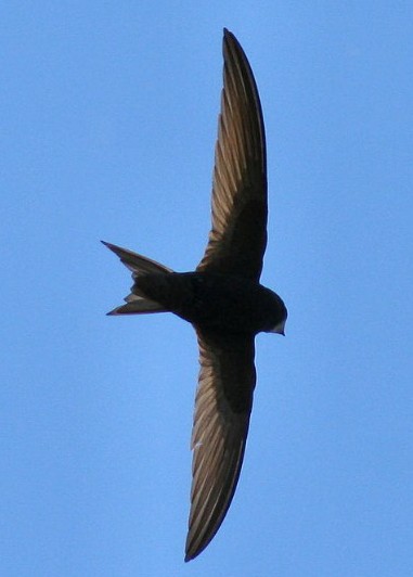
These are birds of extraordinary variety, but not an
extraordinary variety in their appearance. Their appearance is nondescript
rather than extraordinary, a plain sooty blackish-brown with a short forked
tail, a reminder that it's not only exotic birds with colourful plumage
which deserve attention.
Despite the uniform or near-uniform appearance of the
adults and the not so uniform appearance of juveniles, in other respects,
this is a bird of great contrasts.
In the nesting area, adults as well as infants may
indulge in squabbles, but the squabbles are endearing and touching.
Grounded, swifts are more or less helpless. If they are found on the ground,
they have to be given help to fly again, but not if they are injured.
Helping injured swifts is an important part of human care for swifts but not
one of which I've any experience. In the past I've done my best to help
injured hedgehogs.
Once they resume their flight, the swifts are
changed, transformed. Their flight is very varied. The 'screaming parties'
of summer evenings, made up of 10 to 20 swifts, are exultant, exciting. The
swifts which sail in the skies higher than that are often solitaries, and
again, a joy to watch. Better to spend time watching them when possible,
time that is very well spent. As night falls, they go higher and higher. In
this realm, what they do can only be investigated electronically. What they
feel as they fly is completely unknown, of course.
Human navigation is an extraordinary achievement, the
kind of precision navigation achievable by electronic means, that is.
Without the aid of specialized equipment, human navigational skills are
necessarily very limited. It's very different in the case of swifts (and
many other birds.) The navigational skills of swifts, their ability to find
the same place they used for nesting last year, are extraordinary. So much
else is extraordinary in the case of these birds, even if their body colour
is far from extraordinary.
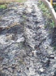
Making a path
I store a ladder at my upper allotment. The area where the
ladder is stored used to be a sea of mud in very wet weather - or at least a
large patch of mud:
I extended the ladder and covered the area of the
rungs with wooden boards:
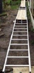
After putting all the boards in place:
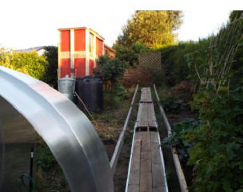
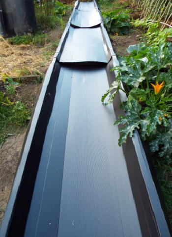
I covered the area taken up by the ladder and a
further area, up to the two lines of vertical boards on either side of the
ladder with sheets of 'Proplex' material, which is waterproof and very
cheap. The water runs down the water-collecting surface and is collected in
a storage container at the bottom of the structure, not shown here. The
water storage container is a galvanized metal container bought at an
agricultural supplies store. Before making necessary adjustments to
the sheet to give a more tidy appearance:
The Proplex sheets can be removed, and replaced, very
quickly. The path after removal of the sheets, with a flower bed to the
left:
Converting a manual apple press into a
hydraulic apple press

This shows a manual press I bought and used for apple pressing about ten
years before I began to design and construct hydraulic presses to convert
apple pieces into apple juice. I still have the press, a sturdy and well
made machine, with wooden slats, a cast iron base and a central cast iron
screw thread, down which the wooden half-circles which exert the pressure
move, turned by a handle which is not shown here. The handle which is shown
is a more slender piece of tubing, with bends not present in the
original handle. Also shown, two very small hydraulic bottle jacks, with
their original straight handles, not used when operating my conversion.
The original machine may have been well built but it was cumbersome and
became more and more difficult to use as the pressing proceeded, as the
pressure plate got lower and lower. It eventually turned into a real
struggle, needing brute force to accomplish.
I decided that there had to be a better way, and found a better way. I
don't explain the small and not so small adjustments needed to operate the
machine with hydraulic power. I'll summarize. The two hydraulic machines
fit very conveniently into the top of the wooden cylinder, with the pistons
in the lowest position, so that the hydraulic machines take up the minimum
space. In the photograph above, they're not in the lowest position.
Below, the two bottle jacks placed on the two semi-circular wooden
plates. Their relative positions enable them to fit into the available
space.
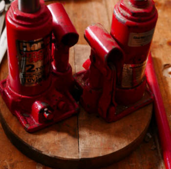
It would be impossible to operate the hydraulic bottle jacks with the
straight handles supplied with them but the bent handle - only one of the
two is shown in the first photograph of this section - allows them to be operated perfectly easily. As the pressing
proceeds, more and more of the piston emerges, the battle jack extends more
and more and the wooden half-circles go lower and lower. The two wooden
half-circles which exert the pressure on the apple bits form the base upon
which the bottle jacks stand.
Instead of a furious struggle, apple pressing proceeds calmly and easily.
This is the machine called the scratter, which I bought at the same time as the apple
press. It's standing on the apple press in the photograph here. The operation of apple pressing is preceded by cutting each apple
into quarters, followed by the feeding of these apple quarters into the scratter. Turning the handle of the scratter converts the quarters into much
smaller pieces, which fall into the wooden container of the manual or hydraulic apple press below
the scratter.
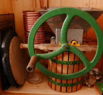
The
PHD workbench
This is the original material. Since it was
published, I've designed and constructed another bench, shown on the Home
Page of the site.
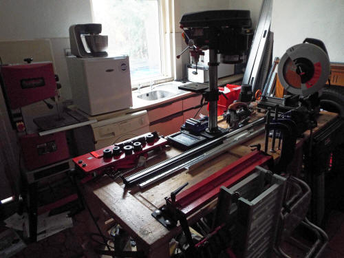
No
innovations are possible in workbench design and construction - everything
that could have been thought of has already been thought of. That's one
opinion, but I don't share it. I'd claim that the PHD workbench does
incorporate one or two innovations. I don't claim, of course, that an
improved workbench necessarily leads to improved woodworking or metal
working.
There's general agreement that a good workbench has to be solid and heavy,
to provide a stable base for holding the wood or metal which is being
worked. I don't dispute that in the least. I think the same. The workbench
I've designed is solid and heavy.
Manufacturers charge much more for very solid and heavy workbenches than
for very light and flimsy ones, but this one is cheap to construct. I had
available an old door for the top of the bench - it had been thrown out and
put in a skip - together with a plywood sheet, but if a free-of-charge door
can't be found, the cost of the workbench is still very low. I put the
door on top and the plywood sheet underneath. Anyone who wants to build a
similar workbench and has a usable door is completely free to do it
differently.
The workbench is also easy
to construct. No woodworking joints are used. The components are fitted
together only with bolts and nuts. The workbench is easy to dismantle and
easy to move from place to
place, or to put into storage if need be by dismantling it.
Workbenches which are solid and heavy are difficult to move. Shifting loads
of this size is a job which should preferably be avoided. Changed
circumstances may make it essential to move a wonderful and very
substantial workbench some distance. There are any number of reasons - a bad
leak in the roof above the workbench, the purchase of a new piece of
equipment which would be better off in the place where the workbench is now.
This
workbench is very easy to move, as I explain now. Workbench design doesn't
have to be like tent design - the ideal backpacking tent is very spacious,
very light, very strong - capable of withstanding gales - very cheap, very
easy to erect and very easy to dismantle. In tent design, far more than
workbench design, the problem of incompatible ends is a real one. In
workbench design, it's much easier to achieve advantages without
corresponding disadvantages.
We can
move the workbench within the workshop or working area very easily, without
taking it to bits. We can move the workbench longer distances by taking it
to bits, something which is very easy. It's just as easy to assemble it.
How do
we move such a heavy object within the workshop or working area? Answer, the
bench has a jacking point. Place a heavy hydraulic jack or a small and light
hydraulic bottle jack or a non-hydraulic vehicle jack under the jacking
beam, at more or less the centre of the beam.
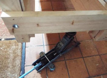
I see
advantages in equipping workbenches, like motor vehicles, with beams which
are strong enough for the purpose. These beams are at the ends of the
workbench, not the sides, of course.
When
one end is in the air, attach blocks to the two legs - or supporting members
- of the workbench at this end. The blocks are equipped with heavy-duty
spindle castors. These castors have brakes, so that once the other end is
raised, the castors don't move. Operate the jack so that this end is gently
lowered and the castors take the weight of the workbench. Go to the opposite
end and do the same. There's no need for the castors at this end to have
brakes. Once this end has been gently lowered, the workbench is mobile.
My
workshop is small and has limited storage space. For this reason, and the
convenience of having tools and materials close at hand, I use the bench
surface for storage as well as a working area. I don't tend to work on large
objects on this bench and a large working area is unnecessary.
A number of my designs have extensions. A strong
structure, whether it's a workbench, an A-frame greenhouse (triangular
structures are intrinsically strong) or a metal framework, can help to
support and to strengthen other structures. In the case of this workbench,
scaffold boards are attached to the bench and to another strong strong
structure, the one which incorporates the sink and cupboard storage units,
forming a bridge between the two. The boards lack the unmoving rock solid
strength of the bench itself, but they are more than adequate for a wide
range of topics. Obviously, the top of the worbench can be cleared, if not
completely, to give more working space.
The
four recesses in the top of the workbench are useful for retaining a
wide range of tools, fixings and other items, largely eliminating the risk
of accidental falls from the bench onto the floor.

Working at a workbench should give the feeling of
being at one with the work. Workbenches often keep the user at too great a
distance from the work, literally. If the long horizontal component at the
base had been continuous with the vertical supports at the corners, then
when feet were touching the long horizontal component, the user wouldn't be
as near to the work as in this design.
There's a great deal of storage space underneath the
bench. My large vacuum extractor is on the workshop floor. Trays at floor
level provide storage space. At the level above this, there's additional
storage space.
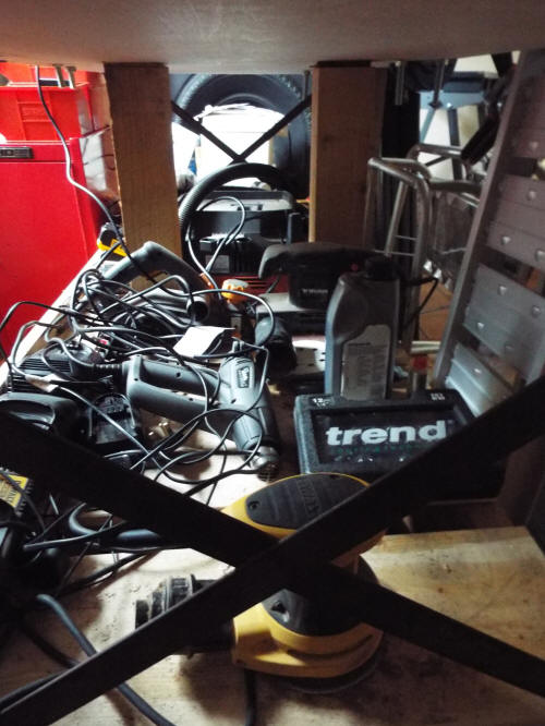
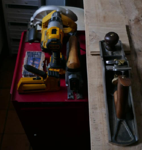
PHD low-level sheet metal workbench
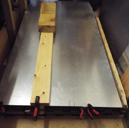
Above, the workbench. The wooden straight edge for guiding
the jigsaw has now been replaced with a metal straight edge, which has the
advantage of greater weight as well as an edge which is more exact. The
workbench is suitable for work with a router as well as a jigsaw.
What are the advantages of having a sheet metal
workbench as low as this? Above all, much greater safety in handling sheet
metal. The sheet metal I have is stored against the wall to the right of the
bench. If I had a bench of the usual 'bench height,' I would have to get
hold of the sheet and lift it on to the bench. A sheet of sheet metal isn't
too heavy but it is large and unwieldy. It flops around in an irritating -
and potentially dangerous - way. The corners of the sheet metal are
protected by my system of plastic clip-on units, more or less eliminating
the dangers but not eliminating in the least the difficulties - these
materials are much more difficult to handle than structural steel bars or
most other things, even for two people. I do need help bringing in the
sheets from outside to this storage area. A fork-lift truck can transport
sheet metal in a horizontal position, but people always carry them in a
vertical position, for obvious reasons. Why should anyone need to take out a
vertical sheet from storage, rotate it to the horizontal position and then
lift this very, very cumbersome thing quite some distance and then place it
on a bench at approximately waist height?
The section which follows this describes my earlier sheet metal workbench -
a good design, I think, in many ways, but with the great disadvantage of
being simply too high.
My bench allows a far easier way of working. I simply get hold of the upper
edge of the sheet - with an extended arm, keeping a safe distance - and pull
it away from the wall so that it falls to the left, onto the low-level
bench. Adjustments are made to the position of the sheet and then the sheet
is clamped to the bench. The clamps shown in the image above are spring
clamps, used in pairs. One clamp grips a wooden support, a scaffolding
board. (The placing of these boards is explained below.) The other clamp
grips the edge of the sheet metal and the clamp which has already been
applied. This system is very, very quick and very secure. The sheet metal
can't move at all. In this stable position, the sheet metal can be cut. For
straight cuts, including long straight cuts, the wooden straight edge shown
in the image above is used. It acts as a guide for a jigsaw. The wooden
straight edge is clamped to the sheet metal at the front edge using one
spring clamp. The straight edge is secured at the far side using a very
simple but very effective method. It's simply weighed down with the two
blocks, which are oak and heavy - heavy enough to allow no movement of the
straight edge during cutting.
Moving a sheet from storage to its position on the bench only takes a
few moments - from a position of safety - rather than a much longer time, in
a position which is potentially dangerous and at the least, something of a
struggle for two people and all but impossible for one. When the work has
been carried out, it's very easy to lift the sheet - or sheets, if the sheet
has been cut into more than one piece - back into the storage position by
the wall. Setting up the straight edge takes only a few moments.
.jpg)
Above, the components of the workbench
The workbench is very simple and very quick to set up, and to
dismantle. The components can easily be stored and take up very little
space. The main components are simply four sections of scaffolding board,
each of them 22cm high, separated by six sections of oak sleeper. Sections
of softwood sleeper can also be use. Each of these sections is 30 cm long
and 10cm high. These sections of sleeper and scaffolding board (longer,
complete scaffolding boards can also be used) aren't joined in any way, by
nails, screws or bolts. The components are simply held in place by two long
pieces of webbing. The ones here are the kind used to secure loads to roof
racks. The components rest on hardboard here, but can also rest on the floor
directly. The weight of the oak sections effectively prevents any movement
during cutting.
Longitudinal cutting of sheet metal is obviously carried out parallel with
the sleepers. If it's necessary to cut the sheet metal in a place where one
of the scaffolding boards would get in the way, the sheet metal is simply
unclamped and moved to the left or right, so that there's no obstruction,
and then re-clamped.
Transverse cutting takes place nearer to the three blocks at the far side. A
straight edge is secured, and the metal can be cut easily.
Another
sheet metal workbench
This section is archived material.
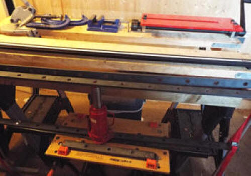
Above, a view of part of the machine
I designed and built for bending sheet metal and for making the cutting of
sheet metal easier. It's also a workbench for general sheet metal work (to
mention just one activity, joining sheet metal sections by riveting) and a
supplementary bench for other work, such as general metalwork and woodwork.
It can be used for joining sheet metal sections by riveting, for example.
It's housed not in my workshop but in another room. The sheet metal is fed
into the machine between the two perforated steel bars. I already owned a
machine for bending sheet metal but the maximum width of the sheet metal
which the machine can bend (by non-hydraulic power) is only 600 mm. This
machine will bend sheet metal up to a width of 1300 mm by hydraulic power.
I made use of webbing straps (one of the two red straps visible here) rather
than steel components when the forces are purely tensile, not compressive. I
think this is a very useful design feature, which can be used in machines of
many different kinds. Webbing straps can withstand considerable forces
without breaking.
When the machine is used for cutting sheet metal, the sheet is placed on top
of the two long and strong boards which form the upper surface and secured
with clamps - there are two G-clamps which can be seen towards the left. To
the right of the G-clamps is another clamp. Its main use is clamping
metal which is being drilled in the pillar drill of the workshop. On the far
left is the equipment which does the cutting (Stakesy's throatless hand
shear.) On the right is a bench swager and slip roller used amongst other
things for strengthening sheet metal. On the nearer of the top boards is a
router guide, useful for measurements of length.
To cut the sheet metal, the cutter is placed within the channel which
separates the two boards, at one end of the channel. The channel is 12 cm
wide and 10 cm deep. The cutting blade is at the correct height for cutting
the sheet metal. In this position, the cutter can be moved forward. As it
advances, the handle is operated to cut the metal with the blade. The cutter
can be used without the machine, but it's much harder to obtain a straight
cut - if a straight cut is the intention. The machine, and the separate
cutter, can also be used for curved cuts. Again, the machine makes the
process easier.
Safety in sheet metal work

Above, reducing dangers in sheet metal work:
unprotected and protected corners of sheet metal sections. Unprotected
corners are very sharp corners, which can kill or injure.
Experienced sheet metal workers know
about the hazards of sheet metal and take good care to avoid them. Even so,
they may well be injured, perhaps when they're very tired and don't keep
well away from the hazards, which include not just sharp corners but jagged
edges of sheet metal.
The companies which sell sheet metal, in my experience, take absolutely no
interest in matters of safety. They may assume that every customer is an
experienced sheet metal but someone who has only recently become interested
in working with this very interesting material is able to take away the
sheet metal, with unprotected corners. Sheet metal comes in large sheets.
Moving them calls for great care, but even with great care care, accidents
can easily happen, when sheets have to be taken up stairs or moved round
corners, for example.
In the lower part of the image here, the corners are made more or less
harmless by the addition of plastic corner pieces. I use the plastic pieces
which are sold to hold together loose printed sheets, easily obtainable from
shops which sell stationery materials. It's just as easy to protect any
jagged edges of sheet metal in the same way, although it will take more of
these plastic pieces.
I'm glad that Dr Marcus Bowman points out the dangers in his book 'Sheet
Metal Work.' It's one of the books on sheet metal work which I own. In the
chapter 'Safety First,' he writes,
'Because the edge of a sheet is so thin, the pressure it exerts is very
high. You might get a nasty bruise or even break a bone if you strike your
hand with a hammer or a large flat piece of metal, but strike your hand with
the edge of a sheet and the injuries are likely to be much more severe ...
'The edges left after a cutting operation usually have a fine, almost
invisible burr which acts like a sharp razor saw ... Yes, the edges of sheet
metal deserve the utmost respect. Whenever possible, avoid handling the
edges of sheets, and atthe very least, wear good, heavy-duty, procetcive
gloves of leather or Kevlar, and do not allow your hand to slide along an
edge.'
He also writes well on the risks to hearing and sight, including this:
'Wear good eye protection made to proper industrial standards at all times.'
He gives many recommendations in the section, 'Creating a safe environment'
including this,
'Watch those sharp corners if you are moving sheets when others are present
...' but of course, there's a need to watch those sharp corners when others
aren't present. It's much better to take great care but to have the sharp
corners made blunt and more or less harmless by such a method as the one
I've suggested.
The PHD solar
wood store
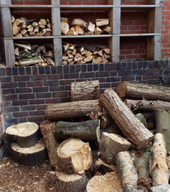
Logs stored in my back yard before construction of
the solar wood store (What I call a 'solar wood store' here is usually
referred to as a 'solar kiln'):
A solar wood store makes use of the greenhouse effect
to increase the environmental temperature, and so increase the rate of
moisture loss from chopped and sawn wood - the process called 'seasoning.'
This is the solar wood store I designed and constructed.
View from the North:
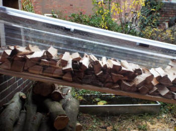
The logs are supported on three scaffolding boards,
which are supported by a galvanized bin on the left and the wall on the
right. The PVC roof is supported by two aluminium C-channels, which are
light, strong and cheap. There are four short sections of C-channel inserted
into the two long sections, to give support to the PVC throughout its
length. Another PVC sheet, placed vertically, forms the wall of the log
store to the South.
View from the South:
View from the West (on the left sections of Larch
logs.)
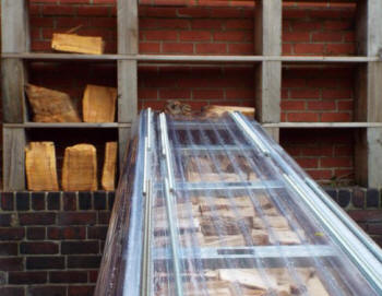
A non-solar outside
wood store
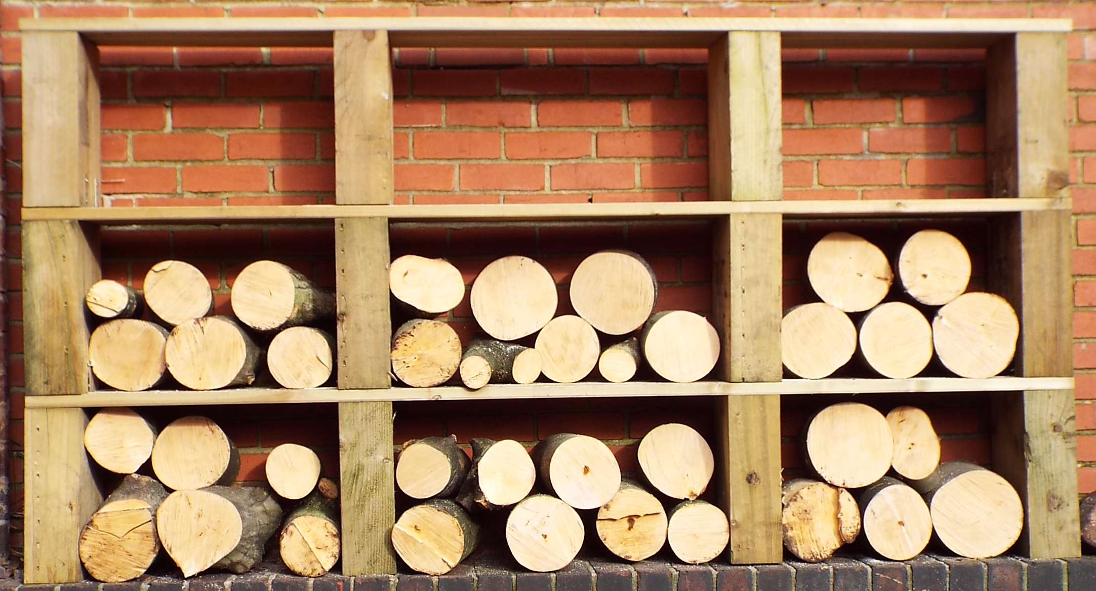
Above, an outdoor project, in the backyard / back
garden - a very simple structure for storing wood to be used in a multi-fuel
stove. The wood store is in my small back garden. The wood store is
constructed from off-cuts of railway sleepers, which support horizontals
made from decking boards. The store still has to be finished with
oil/varnish after it has dried out. The log sections here still have to be
cut into smaller sections for seasoning.
A chainsaw stand
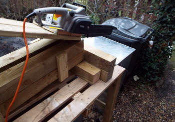
Another outdoor project, a stand for supporting a chainsaw, used for
sawing logs and branches, particularly repetitive sawing. A safer way of
using a chainsaw for tasks like these. This chainsaw has now been replaced
with a better model, a Grizzly chainsaw.
Steam bending of wood
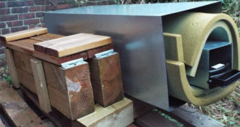

Above, two views of the equipment I made for steam
bending of wood. The wood to be bent is placed in the inner steel container,
which is filled with steam from a steam generator. The container is well
insulated with the foam, inside the larger steel container. Next to the
steam bending equipment, the chainsaw stand.
PHD outdoor oven
The outdoor oven is located in my upper allotment.
A new design, with advantages. The oven can be used for
cooking pizza and for many other purposes. This photo shows the view to the
North. There's a pizza stone placed on top of the oven, which is here at an
early stage of development. The rose shown here is the variety Arthur Bell.
The oven blends with the greenhouse and extensions.
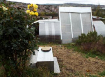
In October, I placed more bricks in the oven to increase
thermal mass. More bricks were placed on the left of the open side, to
reduce the size of the opening. The opening is now 64% of this side. The
figure of 63% is often given as the optimum. I also added a horizontal
section of welded wire mesh to the top of the oven, the section supported by
another section of wire mesh at the rear. The horizontal wire mesh can be
used for various purposes. The primary use is for storing, not seasoned wood
to be used in the oven, but unseasoned wood whose drying will be aided (even
if not very much) by the heat given off by the oven. The roof of the oven
incorporates rectangular steel section, supporting fire bricks. The roof is
well insulated, then, but the stored wood increases the level of insulation.
Very soon after, a curved galvanized sheet was added
to protect the wood, which, after all, is drying, from the rain. It also
improves the appearance.
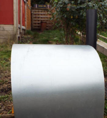
The curvature of the sheet allows it to shed rain
easily but the top of the sheet (which is supported by the wood stored
below) has very gentle curvature and can be used for supporting all kinds of
things when the oven is used - cooking equipment, for example - and as a
work surface. I use it for transferring rolled-out dough to a metal pizza
support before adding the topping. This is much more convenient than having
a table nearby and using that.
The wood stored on top of the oven and on the sloping
metal rack near to the chimney comes from the wood store in my back yard.
The sloping metal rack is just visible in the image below, at the left. This
rack supports the horizontal rack which in turn supports the wood shown
above, hidden from view now by the curved sheet metal.
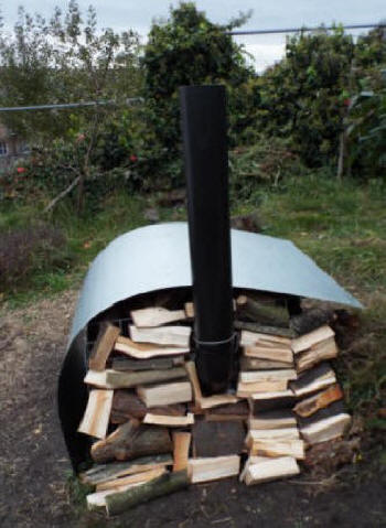
Structure for transporting sheet
materials and long lengths of timber. Also part of van-campervan extension.
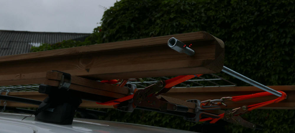
This section was written quite a long time ago. My
van came to a bad end (catastrophic engine damage) and was scrapped. It
hasn't been replaced.
My van is [was] quite a long one, but I sometimes need
to transport things that don't fit in. The roof rack I designed gives me a
means of transporting sheet materials and long lengths of timber safely.
Safety is paramount - avoiding the danger of whatever is being transported
from falling off the rack, and avoiding the danger of the roof rack parting
company with the roof. I've done everything possible to avoid the
possibility, with multiple safety mechanisms.
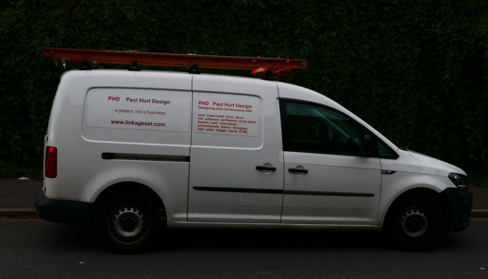
The van - the better side - with roof rack. The
other side has an unattractive hole with untidy edges, caused by someone who
tried break into the van - unsuccessfully - and who had the use of a power tool.
Van-campervan extension
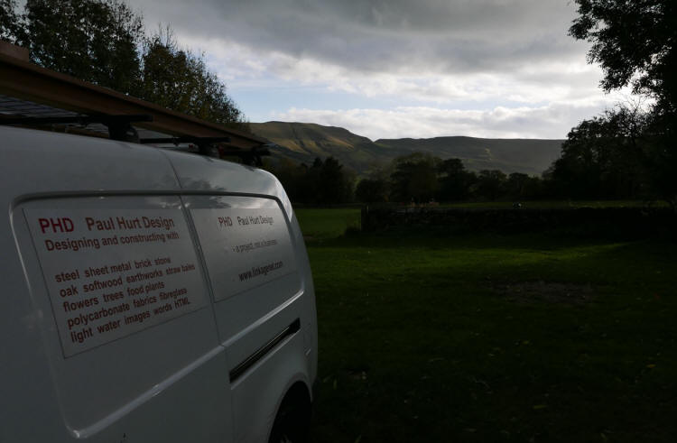
Above, the van at Newfold campsite, Edale,
Derbyshire
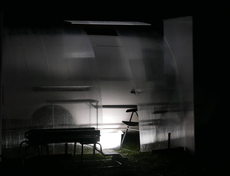
The new van-campervan extension at Newfold Campsite
Edale, an outstanding campsite. The afternoon had been almost windless and
sunny for most of the time but as darkness fell, it started to rain. The
night photographs here were taken in the rain. My first van-campervan
extension had been based on the rear of the van and for quite a long time, I
worked with this location in mind, with strong timber supports extending
from the rear of the van. My ideas changed quite suddenly and I saw the
advantages of a side location , using the twin fluted wooden components
which are part of the roof rack. A much lighter extension was now possible.
The roof rack is used to transport some of the polycarbonate sheets used for
the designed, the curved sheets shown here. The straight sheets fit inside
the van.
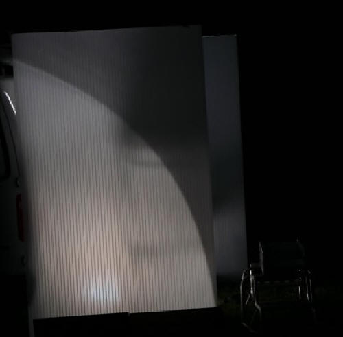
Above, the two vertical polycarbonate components
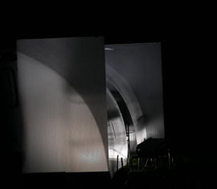
Above, the two vertical polycarbonate sheets and
between them curved polycarbonate sheets.

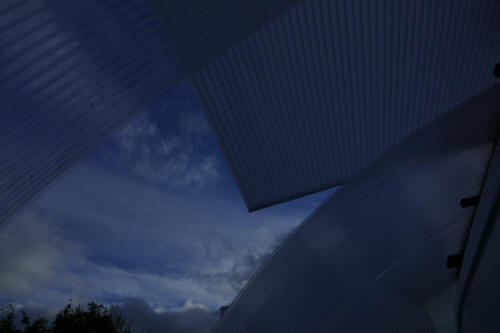
Above, two views from inside the van-campervan
extension
Below, photographs of the van-campervan extension at
Hardhurst Farm campsite, Hope Valley, Derbyshire.
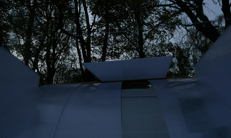
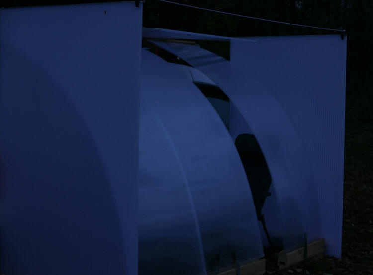
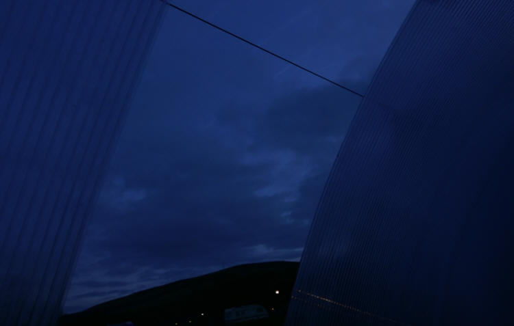
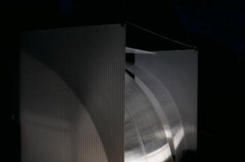
Van - interior fittings
It was only after this visit that I turned my attention to the interior of
the van and designed a layout which made it possible to carry out the basic
activities of camping inside the van, without erecting the external
structures: the basic activities include a place to sit, with enough
headroom - the place to sit is a place to eat as well - a place to sleep,
which obviously must be long enough and wide enough for one person, and
toilet facilities. It would be too much to expect to include cooking
facilities in this very small space. I started with a pallet placed on the
floor of the van which gives a place to store many of the things necessary
for camping. It also gives opportunities for tying down (I prefer chaining
down) itms. Later, I bought a solid oak bench, which shifted and was liable
to turn on its side until I found a method of chaining it effectively.
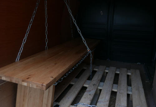
Above, the oak bench which is now a fixture in the van. Shelving is useful
for storage of items during transport and sometimes for longer - but not for
longer storage of valuable things. I believe in practicality and cutting
costs whenever I can but sometimes, it can be worthwhile spending more for
things which have practical value but which also make a contribution to
aesthetics. The oak bench here was very good value for money and it has
practical value. Things can be placed underneath the bench as well as on
top. Large polycarbonate sheets which are used in the van -campervan
extension can be placed on the top and can be transported in a horizontal
position.
After this, it was some time before I made additions to the design to
achieve completion.
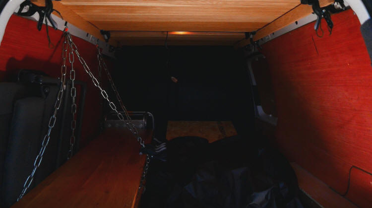
Above, a recent image of the interior of the van. The first addition I
made was to the ceiling. I designed supports for oak boards - usually used
for flooring rather than interior roofing. These enhance insulation as well
as looking far better than the original internal roofing of the van. The
bench is left in place, secured by a new configuration of chains. The two
chain diagonals to the right can be removed quickly to give unobstructed
access. Objects placed between the chains on the left and the left wall of
the van can be transported securely. Here, a folding chair can be seen.
Also visible are parts of two aluminium supports which are essential for
standing on, to reach the roof structure of the van, to put in place or
remove the polycarbonate sheets, for example.
The bench is used to support heavier objects during transport, including one
side of the polycarbonate sheets used to construct the external structures
shown already. There are methods of preventing movement of the bench without
using these side chairs. When the polycarbonate sheets are transported, one
of these alternative methods is necessary.
The bench also forms the 'sleeping platform.' When it's used for this
purpose, the two side chains to the right are obviously removed. The bench
is long enough but not quite wide enough as the. support for sleeping.
Visible in the image is part of an OSB 2 board which is a little longer than
the bench and appreciably wider. It's stored and transported in a sloping
position, with the lower end at the back of the van and the higher end
towards the front, resting on the vertical bulkhead which separates the
driving compartment from the rear space.
Clearly visible is a large flexible storage bag. Its original use is for
storage and transportation of objects and materials, as an alternative to a
rigid roof box. It can be used for storage of things such as a sleeping bag,
a camping mattress and clothes.
Between the pallet and this sloping board there's a space for storage of
other things, useful for storage of quite heavy or very heavy - but not very
large - objects, such a camp stove.
Not visible are some objects stored underneath the OSB 3 board, next to the
bulkhead. At the time the photograph was taken, there was a portable toilet,
enclosed in two plastic components which together make a box, a
container which stores the water for washing, drinking and cooking - and for
supplying the portable toilet, and a wire mesh basket, with many uses, of
course.
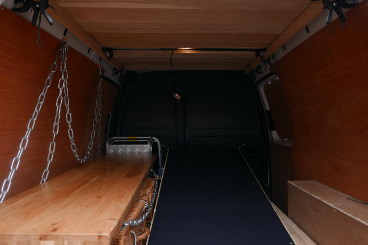
Above, view of the interior showing recent modification to the interior but
without any stored items visible, except for the two aluminium supports
which can be used for access to the roof rack and for other purposes.
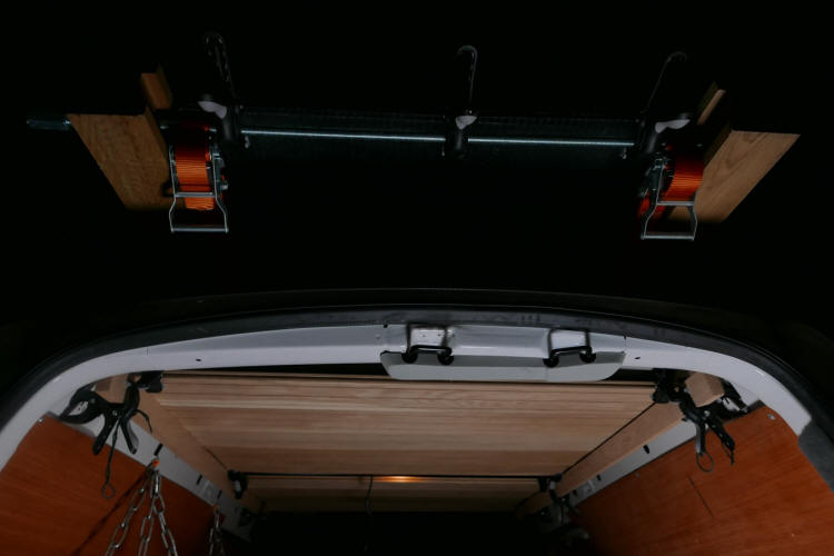
Above, an image which shows some of the interior of the van and some of the
exterior, part of the roof rack structure.
Below, reminders of a previous design, for a van I no longer own, in the
street outside my house, not at a campsite. Some of the designs I've made
and still value have had to be dismantled, are no longer current, but I
still value them - although the second image here would have benefitted from
some simplification of the design, in particular, a less ornate, less fussy
support for the long metal structure.
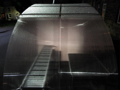
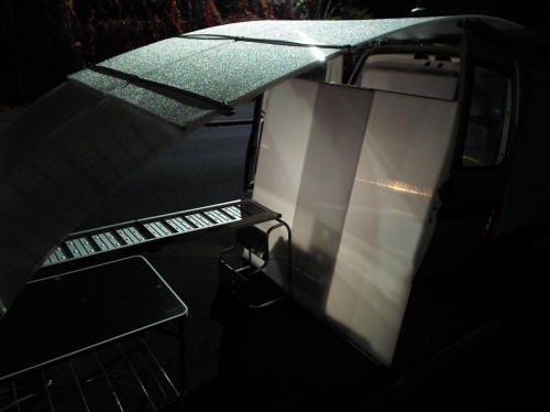
(Indoor) workbench
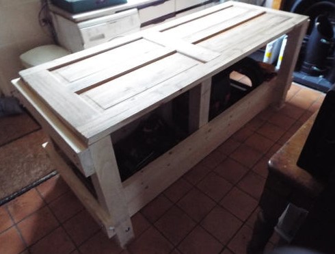
Above, the workbench at an early stage. This has now become a very
different workbench, at least as regards the top. The supports and other
structures below the top are essentially unchanged.
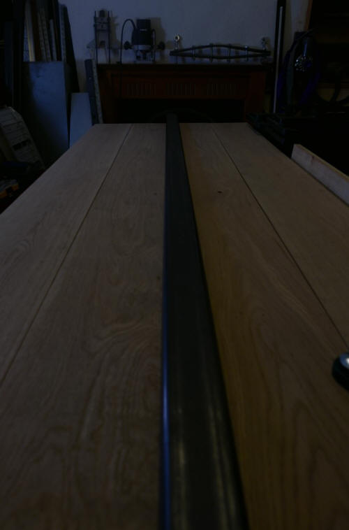
Above, the most recent version of the workbench.
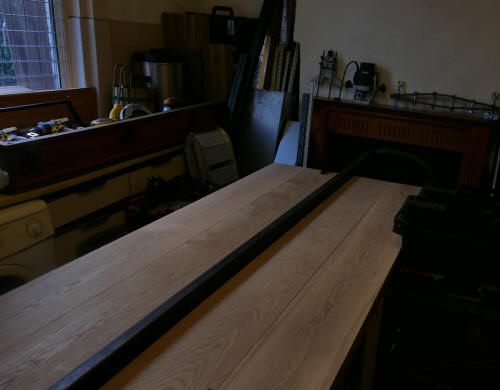
Above, another view.
The dimensions of the workbench:
L 197cm
W 75cm
H 197cm
Before I give details about the construction of the top of the workbench,
I'll explain why I didn't use the two sections of beech I bought for the
purpose. I'd intended to follow the familiar method of planing the beech. To
obtain a smooth, flat surface by this method would have taken a long time. I
have the knowledge and the tools. I would have used my Clifton
five-and-a-half inch plane (made in Sheffield.) I decided that I couldn't
justify the time this would take. I decided that solid, thick, heavy pieces
of wood aren't in general a good choice for the top of a workbench, at least
for many people.
I'm in the older age group. I transported the two sections of beech to my
workshop but their weight is a factor to be taken into account. Each section
is a little more than 4cm thick. One of them weighs 25kg (4 stone), the
other 28.5kg (4.5 stone). A workbench top made up of a single piece of beech
of this thickness, weighing 53kg, would be difficult even for many young and
fit people. This is one factor to be taken into accoun when deciding if a
workbench should have a split-top or not.
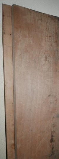
Above, the two sections of beech.
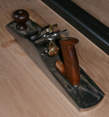
Above, the plane
The top of the workbench (most recent version) has the appearance of
being split but is actually single. The prominent divider running the whole
length of the workbench simple rests on the top boards, secured in this case
by G clamps. The divider here is hollow steel section but dividers made of
other materials can be used. Oak would be a good alternative. The apparent
divider can easily be removed or replaced with one made of other material.
and is made up of layers. Alternatively, the bench top can be really split,
the two sections physically separated. Dividers of different widths can be
used. This facility can be very useful, making it possible to use boards of
different widths.
The
layers I've used to construct this particular workbench aren't a necessity
in the least. A different number of layers can be used, more or less,
depending on availability and cost, of course. The materials making up
the layers can be different from the ones I've used. I used a door simply
because I had a good quality door, a door which was very good value. I
bought it at an antiques shop.
The length and width are the dimensions of the
door which forms part of the composite top surface. Later, I added a plywood
layer, layer 1, with the door above it, layer 2. For a long time, this was
the workbench I used. The door had obvious disadvantages as a working
surface, but the workbench was still very useful - indispensable. The door
became more and more unsightly with use but the workbench was still just as
useful.
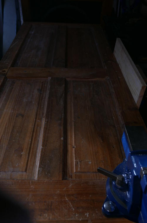
Above, the door. At lower left, the engineer's
vice, useful for woodworking as well as metal working.
The top is thicker now, 9cm (3.5 inch). Layer 3 is
made up of two sub-layers. Layer 3a is a layer made up of oak boards,
thickness 2cm. Layer 3b is made up of oak boards of the same thickness.
This, the top layer, is the new working surface:
Another view of the top of the bench. On the right side of the bench, the
face vice of a radical new design. Instead of exerting pressure on the work
piece by means of a screw thread, I make use of a ratchet strap - much
easier to install, much cheaper, and very easy to use. It's a quick release
vice, releasing the work piece in a second or two. More on the vice below.
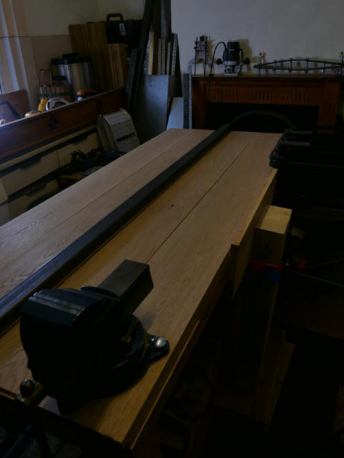
Layer 3a provides the foundation for layer 3b, the working surface A
single layer resting on the door wouldn't be adequate. Layer 3b, the actual
working surface, will become more and more unsightly but still just as
usable. If appearances are important, rather than removing any deposits and
sanding the surface, there's a quick and easy way to restore the original
look. The top layer could be removed and replaced with new oak
boards (or reclaimed oak boards which will provide a good or adequate
working surface.) Easier still - simply switch the two layers. Layer 3a will
still be smooth, unmarked, unstained - it becomes the new working surface.
Layer 3b becomes the lower layer and it's hidden from view, of course. Its
appearance isn't important. If holes have been drilled through the top of
the workbench to secure heavy tools, such as a vice, but you think that the
vice would be better somewhere else on the bench or should be removed from
the bench, only the holes in the top layer can be seen. The holes in the
lower layers can't be seen. Simply replace the board or boards in the top
layer or remove a small section of the board or boards and replace with a
new section or sections.
The workbench is very, very easy to construct. There are no
woodworking joints. Instead, I make use of bolts. The workbench is very,
very easy to take apart. The workbench is heavy but none of the components
are heavy. Reassembly in a different place is very easy. The workbench can
be moved inside the workbench without the need for disassembly and
reassembly. The corner vertical supports have holes drilled in the base so
that stem casters can be inserted into the holes, after each end has been
lifted up using a hydraulic jack.
The workbench has substantial storage space. I use it for storage of tools,
drill bits, nuts and bolts, screws, clamps and many other things. My
workbench vacuum extractor for removal of wood dust is stored there. In
general, items are placed on storage racks which are part of the internal
structure of the workbench rather than inside the structure but on the floor
of the workshop. This is so as to increase the mass of the workbench,
although the workbench is fully stable, not subject to vibration, even
without the added mass.
Below,storage containers in a space on the side of the bench under the
overhang:
The original plan of the workbench
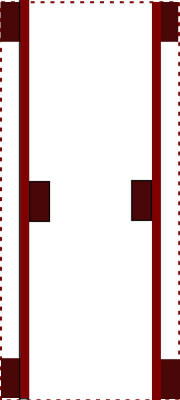
was modified. I intended the top of the workbench to extend to the outer
edges of the four corner supports, with no overhang. This is still the case
on the right side (and the top and lower sides.) An overhand on the right
side would make it impossible to install and use the new face vice. On the
left side, the top protrudes: there's now an overhang of 4cm. The section of
oak board (two layers, 4cm total thickness) makes it possible to use clamps
here to secure material for sawing and other operations. For holding
material, I favour the use of vices - the engineer's vice and the ratchet
strap vice I designed - and G-clamps of different sizes and spring clamps of
different sizes.
Below, spring clamps securing wood before sawing.
(The saw is made in Sheffield, by E. Garlick and Son.)
Larger sizes of wood
need larger clamps than these. The extension to the bench can support quite
heavy pieces but not very heavy ones.
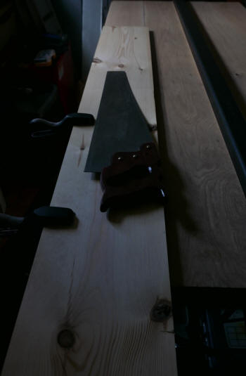
Modifications to the workbench include not just a new top surface but the
addition of a new kind of vice.
Another PHD bench
This is very similar to the earlier bench. I make use of larger supports,
sections of larch sleeper, each 80 cm long, at the corners. The bench top is
200cm long and 90cm wide. There will be two further supports at the mid
point of the bench, as in the earlier model. For this bench, I used screws
rather than bolts. Although the earlier bench can be constructed quickly,
for this bench, speed of construction was very important. I needed to be
able to use the bench as soon as possible for a project.
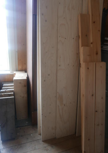
Above, wood for constructing the bench in storage, not all of the wood
shown here needed. On the far left are sections of oak sleeper. On the
right, not all the sections were used (as horizontal connectors) but another
longer length (200cm) was needed. To the right of the sections of oak
sleeper (60cm long), the sections of larch sleeper used in the project (80
cm long), and the plywood sheets (200cm) long used for the top of the bench.
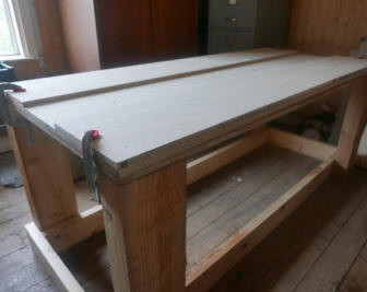
Above, the first stage in the construction of the workbench - the basic
structure. Getting to this stage takes very little time. The sections of
larch sleeper are placed at the corners - they are self-supporting and will
stay in place without falling over. The horizontal sections at floor level
are added and secured with screws. The top of the workbench consists of two
layers of plywood 90 x 200 cm secured to the sections of larch sleeper at
the corners with screws and two movable / easily removable narrower pieces
of plywood held in place with clamps. There are various advantages to this
system. For work which needs a flat, continuous serface, the narrower pieces
can be removed quickly.
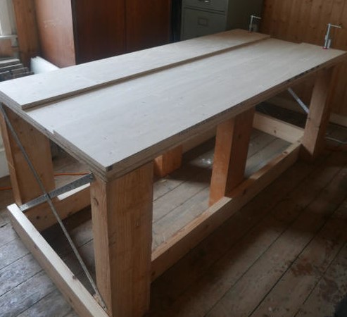
Above, the next stage: adding sleeper-sections at the mid points of the long
axis to provide support and to prevent sagging, the supports iset, towards
the centre, to give support nearer to the centre. Addition of crossed metal
bars at both ends. With these additions, a workbench which was able to sway
a little becomes absolutely firm, rock solid, with no detectable swaying at
all.
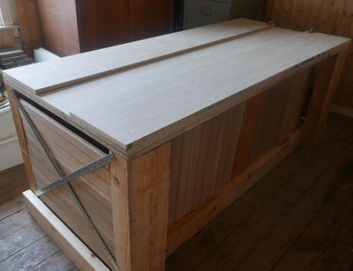
Above, after installation of oak boards, which conceal the items stored
inside. There are four sections of boards on the sides, two on each side,
one on either side of the vertical support at the mid-point. I intend using
the storage space for general storage, not storage of tools or equipment,
but one or more board-sections can be removed for quick access to the
contents. The boards at the ends are fixed but when boards at the sides are
used, as here, they can readily be removed for access.
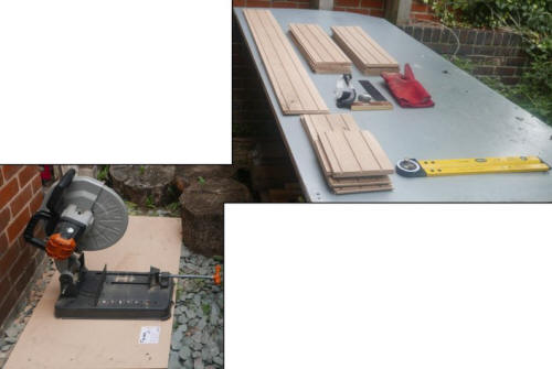
Above, the oak boards were cut to length outside. Only part of the image
shown here, the essentials - the machine on the left, designed by
'Evolution,' based in Sheffield, and the sloping workbench on the right,
with a board waiting to be sawn at top left, boards already sawn at top
right and offcuts at lower left.
Working outside has advantages, if, of course, the weather is suitable -
no rain. The dust released by sawing oak is hazardous indoors, much less
hazardous outdoors. The sawing machine is heavy, but there's no need to lift
it to the height of a workbench. Sawing by machine can be carried out just
as well at ground level. If work will take a long time, low seating can be
used.
Below, machines and tool storage near to the back door. The machines
include the power saw at the left side of the door, on a movable support,
with castors (not visible here.) When the door is opened, the saw can be
easily moved to the yard / garden outside, where the dust from sawing -
usually oak - is far less harmful than it would be if the machine were to be
used inside the workshop. The saw is left on the low trolley - a form of
simply moveable 'low level' workbench. It can be used very easily, sitting
on one form or another of suitable seating, such as a low wooden stool or
the metal support I use. There's no need at all to lift the heavy saw to the
workbench I have available in the outside area, no need to risk back strain.
I use the workbench for a different purpose, simple as a convenient place
for the simple tools I also need for the work, for goggles for eye
protection, for the oak sections I'll be sawing and the sections and offcuts
which are the result of sawing. On the right here is the bandsaw, also on a
support with castors. It can be moved outside for use when needed, although
that takes longer than moving the much smaller saw. Again, there's the
advantage of vastly decreased problems to do with wood dust.
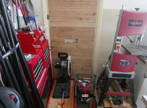
A face vice of a new design
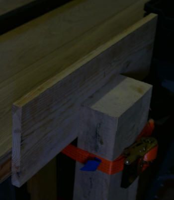
Above, a new design of mine: a face vice which is very easy to install, very
simple, very cheap, very easy to use, very flexible - able to hold
work-pieces of very different size - very quick to use, including quick
release, a radical design which uses a ratchet strap rather than a screw to
exert pressure on the work-piece.
This new design didn't involve
a long period of gestation. The ideas came quite quite quickly. Once I had
the ideas, the vice obviously had to be constructed and tested. Would it
work? Would it hold wood firmly, without any movement, when woodworking
operations are carried out. It took very little time to construct. I made a
modification in the design, removing a component which was found to be
unnecessary. When I tested it, I found there was a little movement in the workpiece. I came up with an idea for a solution the same day and tested the
vice again the same day. This time, there was no movement in the workpiece
at all. The solution involves use of a cheap and simple component I already
had. For the time being, I won't say what it is, but it's a small tool
without any moving parts, without any parts at all, something I use as part
of wood processing to produce usable wood for my stove.
The part in the interior of the workbench, hidden in the image above, is as simple as the exterior. The ratchet strap fits round
one of the workbench supports. There are 6 of them, shown in dark brown in
the diagram. The support is the one in the diagram in the middle row, on the
right, inset. The broken line shows the edge of the workbench top.
Another advantage: the vice is much, much cheaper than a face vice with a
screw and it's so much easier to fit.
Below, assorted ratchets, ratchet straps and cambuckles of various lengths,
widths (25mm, 35mm, 75mm), strengths (up to 10 tonne) and, of course,
colours. I've used ratchets and cambuckles extensively in various projects,
including log-splitting and apple pressing machines.
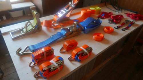
Outdoor sloping workbench
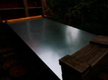
This is a fixture of my small back yard. I prefer to
work in the open air if I can and if the weather is good enough. My workshop
is cramped and sometimes I work with materials which
produce harmful dust, in particular oak. I have protection equipment - a
head covering with powered air intake and filtration - but I still prefer
harmful dust to settle outdoors rather than inside. The surface is sheet
metal and is sloping. I find that the slope has far more advantages than
disadvantages. In only a minority of operations would the slope be a
disadvantage. The fact that the slope sheds rain is an obvious advantage.
The workbench shelters things stored beneath it. I use the space for storing
sections of oak.
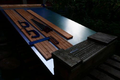
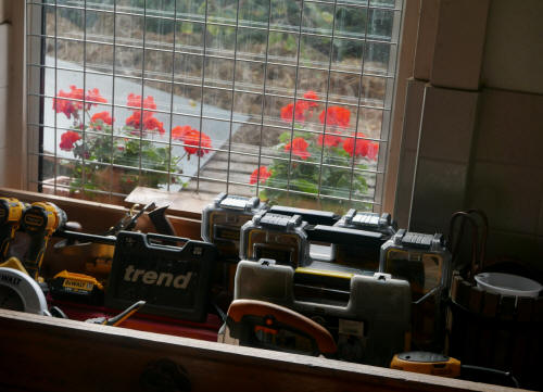
Above, why this room is no longer usable as a kitchen. Why the kitchen is
now upstairs. Tools stored in the area above the kitchen sink. With view
through the window, showing Pelargonium (Geranium plants) growing in a
container on the outside windowsill, the sheet metal sloping workbench and
the backyard, converted into a small back garden a long time ago. The soil
is covered with a thick layer of straw. There's a plum tree in the area, not
shown here.
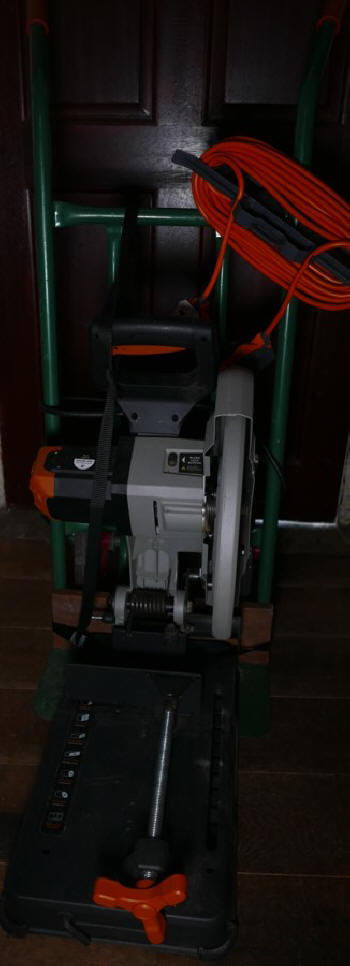
Above, the power saw on its trolley
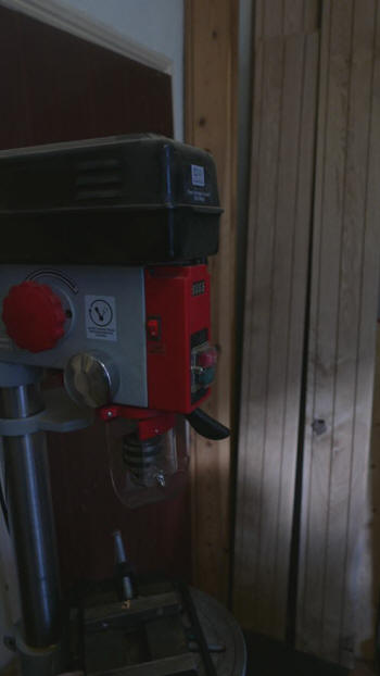
On the right, a few of the oak boards which need
sawing, near to the drill press.
In the section above: some disadvantages of working
indoors, including lack of space (in my workshop) and the hazards of dust. I
use a very versatile power saw manufactured (but not in Sheffield) by
Evolution (headquarters in Sheffield.) I use it far sawing wood, including
oak and larch sleepers. These are 200mm wide and 10mm thick - the width is
just above the maximum dimension given in the specifications but I can use
it perfectly easily. After the first cut, there's a short uncut part left.
After turning the wood over, it's easy to cut the remaining part. I use it
for sawing metal too, most often for cutting rectangular steel section and
perforated steel bars.
For a long time, this amazing machine has been
mounted on a very good portable folding workbench next to the workbench I
desined and constructed. The disadvantage has been that wood chips and dust
and metal fragments are scattered far and wide, on the bench and floor. I
constructed a polycarbonate shelter which partially enclosed the machine, to
confine the wood chips and dust and metal fragments so that it was easier to
use my vacuum machinery to clean up the waste.
I've now put in place a system which suits me far
more. Now, I can move the machine outdoors and use the machine
outdoors much more easily. The machine stays on the trolley. It isn't moved
outdoors on the trolley and then lifted on to the outdoor work bench (which
includes a flat area as well as the larger sloping area.)
Working at a level much nearer the ground is quite
easy. Low-level seating is needed, of course, a low stool or improvised
seating. One advantage of working at a low level is that heavy materials,
such as long oak sleepers, don't need to be lifted to a workbench of the
usual height. I have a great many long oak boards which need to be sawed to
length. Although each one isn't too heavy, the cumulative effort of lifting
them one after the other has to be taken into account. For people in an
older age group, like myself, the decreased effort is important.
The tiller / cultivator and the power saw would be
stored upstairs, in the storage room, if only there were enough space, but
it's more practicable to store them in the workshop, despite the lack of
space in the workshop. In the workshop, they can easily be wheeled out of
the room on the trolleys if more free space is needed.
In the workshop, there's ready access to the
workbench (which has plenty of storage space, but not unused storage space)
on three sides. The narrow 'walkways' in the workshop are quite easy to use.
I'd commend the use of trolleys for storage in workshops like this one, not
spacious but with adequate (just enough) space.
The manufacturer's wheeled attachment
for transporting the garden tiller / cultivator costs about £100. This device is more versatile
- I can use the trolley for other purposes, not only for wheeling the
machine from one location to another. Although I can use my van to transport
the machine to the land I rent, the path to the land isn't a short one, and
carrying the machine this distance isn't feasible for me. The land is only
10 minutes walk from the house and this trolley conversion makes it possible
to transport the tiller / cultivator to the land without using the van.
I've been using a spade to cultivate the land for many, many years and
although I'm in the older age group, I'm still able to do the job using hand
tools but I've come to the realization that digging the growing areas by hand would take up far too much of my time and
there are so many demands on my time.
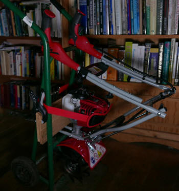
The handles can be folded - here in the 'above' position rather than the
'below' position.' The tops of the handles fit neatly inside the verticals
of the trolley. The machine is prevented from falling forwards by the
sections of oak board, which keep in place the 'front loop handle'
(not visible here), and, also the red and black strap. The machine can
easily be lowered to the horizontal position needed when oil is added to the
reservoir.
Early hydraulic press for apple-pressing
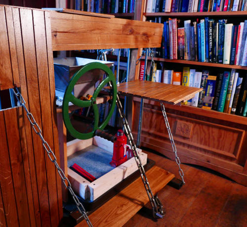
This press has been dismantled. I found designing and constructing it a very
interesting, in fact compelling experience. It worked, it pressed apples to
produce apple juice, but I wanted a press which could also split wood - the
wood-burning stove is in the same room. This press couldn't achieve that.
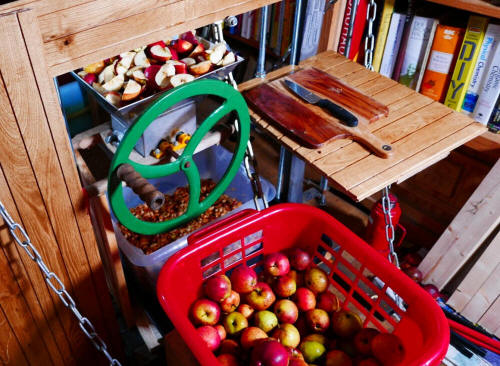
Whenever possible, I like to design and
construct equipment intended to carry out one particular task to also make
easier or make provision for other, related tasks. The image above doesn't show
the hydraulic press in action but it does show the provision for work which
comes before apple pressing: space to store a quantity of apples before
cutting, a small table, with chopping board and knife, used for
cutting the apples into quarters, reducing the apple pieces to smaller
pieces by using the 'scratter,' the machine operated by the green handle
here.
Below, the hydraulic press in action, or the upper
part of the press in action. Shortage of space makes necessary carrying out
some operations wherever space can be found, in this instance, in the front
room where most of my books are kept.
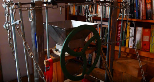
Later hydraulic machine for pressing apples and
splitting wood
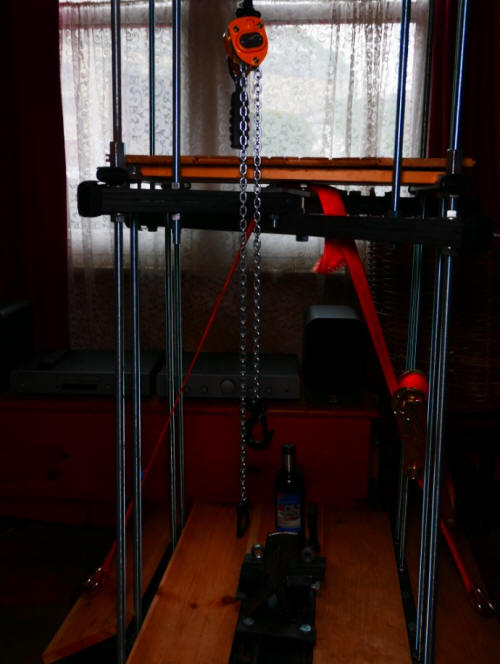
This hydraulic machine is versatile. It achieves
what I wanted to achieve - a machine which can split logs as well as press
apples. Splitting logs is the more demanding task by far. It has facilities
for storing some apples before working on them, the oak surface higher up,
also used for holding the chopping board and cutting the apples into
quarters. The scratter machine, with handle, is fixed to the side of the
machine but isn't shown here. The machine is very easy to construct
(although it wasn't easy to design.) It makes use of threaded rods, which
are easily available, and sections of perforated metal bar. It has castors
for moving from place to place. If it needs to be moved to a location
further away, it can easily be dismantled. Threaded rods are slender things,
of course, but the machine is designed to have the strength needed to
withstand the forces. Only some of the machine is shown. The machine is
1.94 metres tall and at the top, there's a metal frame which can be used to
support sheets of polycarbonate. This system is used if the machine is
outdoors. The polycarbonate sheets can shelter the machine and the people
using the machine. With the addition of suitable walls, a small building can
be quickly constructed.
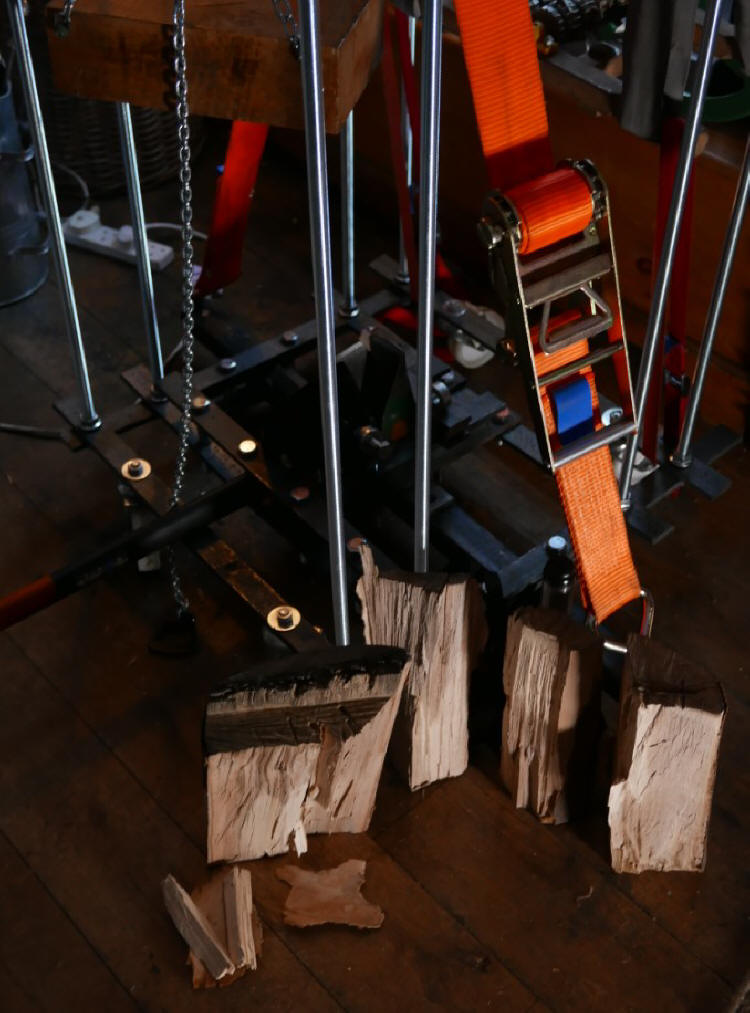
After removal of the wooden boards of the lower
platform, the metal frame is revealed. The perforated bars can be put
together quickly. The threaded rods fit in holes of the perorated bars. The
handle of the splitting axe can be seen. The cutting edge of the axe forms
part of the cutting head.
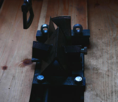
This component, the cutting head, is used when
the machine is splitting wood, not pressing apples. The cutting head gave
rise to greater problems than any other component of the machine. I
originally used a single cutting edge. I tested the machine on a variety of
sizeable logs and the machine was able to split them all - but in every
case, only into two pieces. I wanted a machine which could split logs into
multiple pieces. I eventually designed and constructed the cutting head
shown here, with multiple cutting edges. One belongs to the wood splitting
axe, retaining the handle. The axe can still be used for splitting of wood
by hand, after removal from the cutting head. Another cutting edge comes
from a maul. In this case, I removed the handle. Another cutting edge comes
from a triangular cutting wedge, with subsidiary edges as well as the main
edge. After many attempts, I found a way of fitting these diverse edges
together securely.
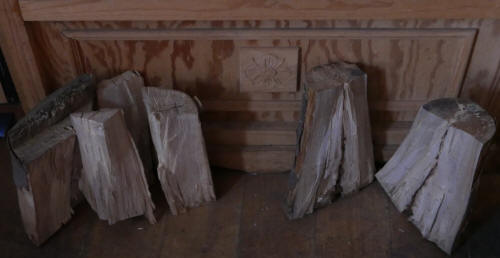
Splitting logs using the hydraulic machine, on
the right into two pieces, on the left into multiple pieces.
The machine is very versatile, with various
configurations.
As there are castors, the structure can easily be moved.
The machine shown above has three horizontal board-layers: a
'two storey structure.' The uppermost board-layer can easily be removed,
with the threaded rods which support it, to form a 'one-storey layer with
two board-layers:
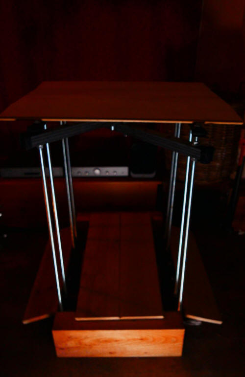
Below, in use as useful furniture. To the right, a
low table of non-standard design, the horizontal board supported by a
basket.
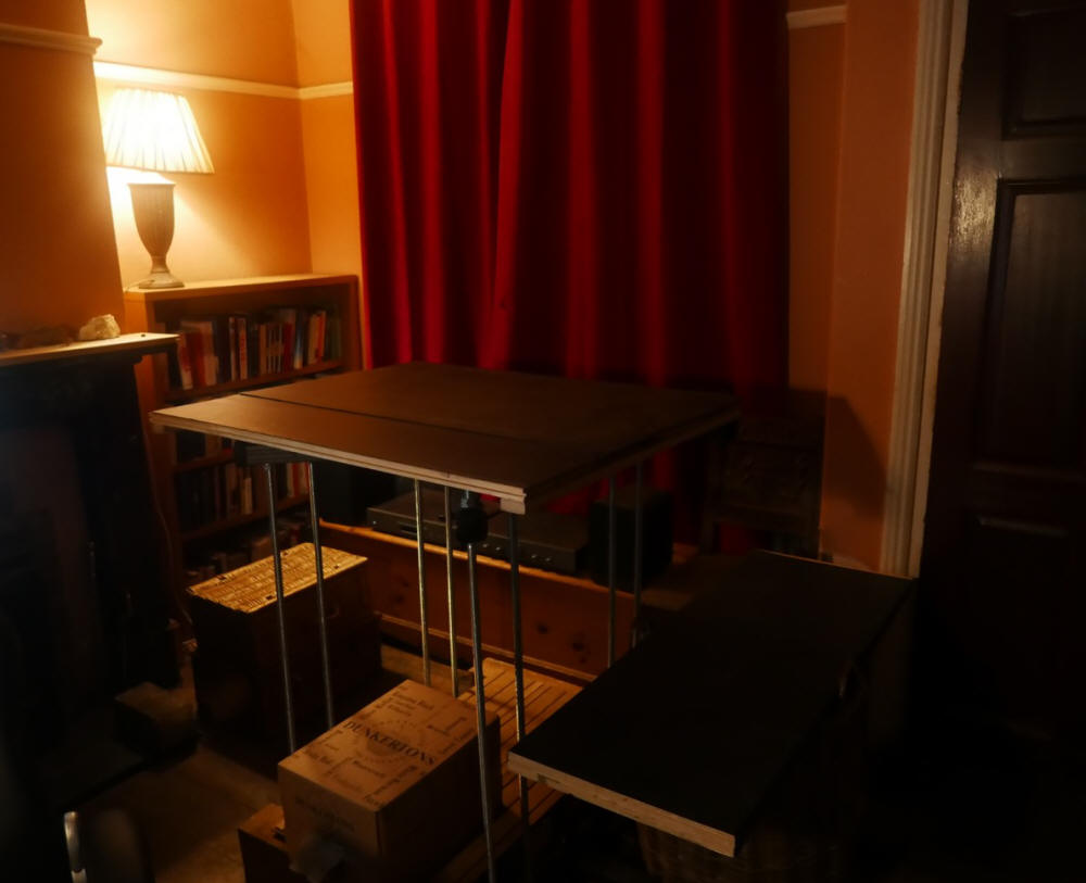
Both the two-storey and one-storey configuration can
be used for pressing apples and splitting wood.
The configuration for pressing apples to produce
apple juice (and pulp) is obviously different from the configuration for
splitting wood. Converting the wood splitting machine into an apple pressing
machine involves removing the cutting head and inserting boards into the
lowest horizontal layer ('board-layer 1,') This rests on solid supports
which in turn rest on the floor. This resists the force of the hydraulic
jack much more effectively than other arrangements, such as a lower layer
supported by legs at the corners.
On board-layer 1 are placed such components as the
tray for juice-collecting, the racks which are separators between the layers
of pomace and the top plate.
The layer above this, board-layer 2 can be used for
cutting the apples into quarters (from a standing position) on a chopping
board placed on these boards.
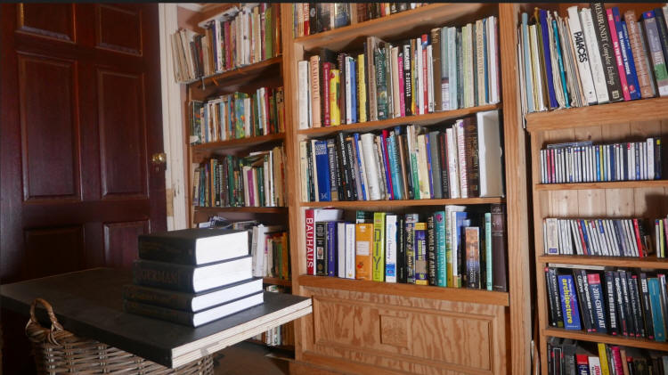
Above, The Book Table, supporting actual books here. The 'pages' or core of
the table is made of plywood layers and the black 'book cover' is made of
material generally used for protection of surfaces whilst working.
The PHD A-frame support and crane
My earlier page on PHD projects has a section on 'the PHD A-frame support
and crane'
www.linkagenet.com/phd/phd.htm#crane
but since then, I've increased its functionality as a crane. In the original
design, the structure was placed against a wall for lifting objects. This
image from the earlier page shows the simple crane lifting the head of a
pillar drill. It would have been far too heavy for me to lift on my own -
the manual makes it clear that this is a two person job.
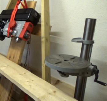
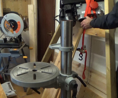
Obviously, a structure with two legs isn't self-supporting but for this use,
the wall provides the necessary support when the structure is leaned against
the wall.
It would be easy, or relatively easy, to make a self-supporting
structure by adding another leg, a tripod, or a structure with four legs,
but a structure with just two legs has the significant advantage of allowing
less restricted access. The more legs, the more difficulty in lifting
larger objects. A crane with two supports or just one support is
perfectly feasible, but the base and the pillar or pillars need to be
substantial, with weight penalties. The crane is light and very easily
transported. The wooden legs can be carried easily with one hand, with the
metal hoist with lifting mechanism carried in the other hand.
I've now designed a crane which retains the two legs but is usable away from
a wall. In the photographs below, the crane is used to lift a log to a
convenient height for putting into the van. The crane can lift much bigger
objects and much heavier objects, to a maximum load of 250 kg.
The hoist I have is a good quality
one but operating the lever to lift the log section takes time - but anyone
with a bad back, anyone with a concern for safe working in tasks like this,
anyone who takes a cautious view of working, may well appreciate the
advantages of the machine - and it is a machine, a device for doing work, even
if it's a simple machine.
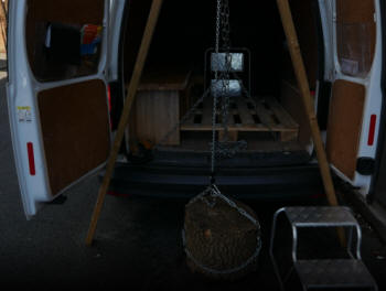
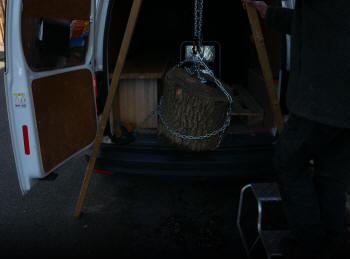
The van isn't a substitute for the wall which provided support in the
earlier use of the crane, in the workshop. The A-frame doesn't lean against the van, using
the van for support and the A-frame isn't vertical. It's tilted away from
the van. The angle can be altered easily. For
many use, particularly with objects much more bulky than this log section,
the object needs to be further away from the van, nearer to the ground, before lifting and during
lifting.
In the load compartment of the van, there are tie-down rings used to secure
loads, usually with straps. The A-frame crane is prevented from falling to
the ground by chain, secured to the two tie-down rings at the back of the
van.
The van provides a secure attachment point for the chain. The crane can be
used in this way away from the van, provided that a secure attachment point
is available. Another possibility is a heavy workbench which can
be relied upon not to move. Yet another is a heavy, immovable rock, provided
it can be encircled by a strap or chain.
Obviously, any straps or chains used for these applications have to be
strong enough, more than that , much more than strong enough.
The crane can be used away from a vehicle, of course. There are various ways
of providing a secure anchorage for the chain. A tree can be used - a fairly
slender tree may well be sufficient. If the ground allows for the insertion of a ground anchor, or better
still, two ground anchors - the use of two ground anchors as attachment
points for chain or rope will give addded security - the A-frame can't fall
in any direction. Two strong ground anchors, each 45cm long, not
including the top part above ground, rotated to insert the ground anchor.
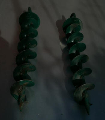
A light crane, easily transported, carried by hand if necessary, capable of
lifting loads up to 200 kg in the case of this model, has many, many uses.
Lifting logs or sections of logs to a vehicle is just one use.
Once a load has been lifted to the required height, it's likely that it
won't be in the required position. How is the log section which has been
lifted in the example her to be moved into the van, where it can be stored
and transported?
Different methods are available but a very useful one involves use of a
horizontal or sloping platform. I have a lightweight one which folds up.
Here, most of the platform is inside the van, with some of it projecting to
the outside. The part outside the van can be supported on a trestle or
other support, or the far edge can be secured so that the platform has the
form of a cantilever.

Since these photographs were taken, I've constructed a new crane. The
prototype was made very quickly. I'd good reason to believe that the crane
would work but it was possible that there would be unexpected difficulties.
At this stage, attention to finish and detail would have taken up too much
time. I drilled the holes towards the top of the two timber sections with a
hand held drill, without attending to the exact placing of the drill holes.
For the new version, more care could be justified and I used my
floor-standing pillar drill, which allows drilling to be much more accurate.
Even so, the prototype worked perfectly well.
Below, one of the wood stores in my workshop. The two parts which make up
the new crane towards the left, fastened to the wire mesh panel with chain,
the older crane next to the pillar drill press. In the centre, the hoist
which hangs from the bolt at the top of the new crane. Also shown, oak
boards, used for a wide range of projects, most recently for renovating and
extending the surface of the computer desk and for constructing a bookcas.
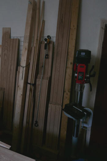
Below, another view:
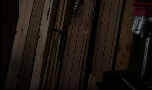
The Workshop: extracts from a panorama
The workshop is used for storage as well as working, storage of machinery,
tools, wood, metal, fixings and many more things. Upstairs, a room of
similar size to the one shown provides more storage space and it wouldn't be
possible to store very much more there.
None of the stored items are out of reach. There's a narrow 'path' on
three sides of the workbench and it's possible to reach almost all the
stored items in the workshop easily. Although the workshop hasn't very much
free space, I don't find it cluttered. The workbench has an important role
here, apart from its use for storage - many, many things are stored
underneath the workbench. Except when I'm using it for its primary
purpose, working in wood and metal, I keep the surface clear. It provides an
'expanse,' a clear area in contrast with the masses and detail on most of
the horizontal surfaces and many of the vertical surfaces.
In landscape design, I provide 'expanses, areas of repose which contrast
with the fullness and detail of other surfaces.
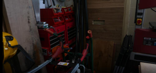
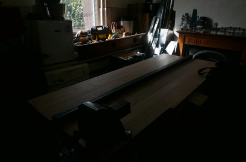
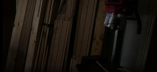
PHD bookcase and renovation and extension of the top of a computer desk
Information about these two projects in this section. Oak boards are used in
both projects. The bookcase and the computer desk are near each
other in the room, which is next to my workshop.
The top of the computer desk was, and is, melamine. The computer monitor I
had on the work surface was, and is, quite heavy and with time, the top has
acquired an obvious bend. That was one reason for resurfacing the work
surface with sections of oak board. A more important reason was to extend
the top layer. I wanted to use two large monitors, not just one, but two
monitors couldn't be fitted onto the existing top.
I work extensively on Large Page Designs but a single monitor is adequate
for working on a Large Page Design. I use a dual monitor system now for
other reasons. The advantages of having two monitors connected to the
computer are very, very substantial, The mouse pointer can sweep from the
left hand screen to the right hand screen with complete ease. I can copy an
extract from a document on the lift hand screen and paste it into a Web page
which is open on my Web page creation program very quickly. This is only to
begin to give the advantages.

The base of the two monitors fit on the new oak work surface, without one
monitor obscuring part of the view on the screen of the other monitor, but
the screens themselves do project beyond the sides of the computer desk top.
Unless they're secured, the monitors can easily be toppled when walking near
them. I've ensured that this can't happen, by clamping the bases to the oak
surface and by using two more clamps to secure the oak surface to the
melamine surface of the computer desk.
Below, the bookcase, soon after construction, with two of the shelves not
yet fully used. The decorative fluting of the verticals clearly visible -
the shelves also have these grooves.
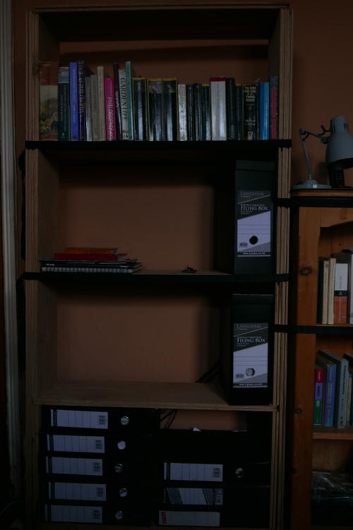
Below, part of the bookcase on the left. Next to it, a smaller bookcase and a taller
bookcase at the right, both of them bought, not made by me. In the
foreground, a view of the oak top of the computer desk with the two large
monitors on the desk, seen from the rear.
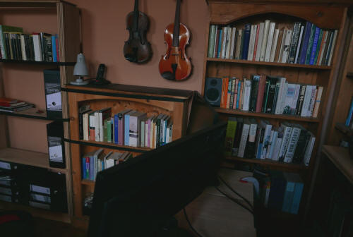
Below, a view of the computer desk from the front, with a view of three of
the eight bookcases in the room. (There's another bookcase outside the door
to the room, at the bottom of the stairs.) The black straps across the
bookcase on the left are visible. These connect the bookcase with the
new bookcase, not visible here.
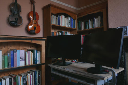
The new bookcase is plain, but it does have decoration on the sides and the
top - fluting. Its main advantage is that it's very, very easy
to make and very easy to dismantle. Once the oak boards have been sawn to
length, the bookcase can be erected in about ten minutes. Dismantling takes
a similar time. The only tool needed is a handsaw, although power tools can
obviously be used. The components - oak boards, a single larch sleeper and a
few straps - are easy to transport. Despite the fact that oak is used, the
bookcase is very cost effective. The decorative fluting arises from the
design. It's far easier to implement than any of the traditional or more
modern woodworking techniques, such as using a router.
The oak boards
come with tongue-and-groove projections and channels. The boards are simply
installed in a way which gives a view of the lines of grooves, the lines
running horizontally and vertically on the structure, giving the appearance
of decorative 'fluting.'
The bookcase is made almost entirely of oak boards - with no
screws, bolts or nails, no fixings of any kind - apart from a base of larch
sleeper and some straps. I didn't cut the tongue-and-groove joints and in
fact, these joints play no part in joining boards. There are other projects
where the tongue-and-groove joints of the oak boards do link boards, but
again, the joints weren't cut by me. I haven't used tongue-and-groove joints
or the related mortise-and-tenon joints, or dovetail joints, or any of the
woodworking joints apart from the very simple butt joints, in any of my
projects. I recognize the usefulness and attractiveness of the classic
woodworking joints, but the emphasis is upon ease of construction, for
anyone who cares to make any of the designs. The process of design and
construction of prototypes, the work of refining and improving designs, has
almost always been long and arduous, and to have included woodworking joints
would have taken me away from the fundamentals.
One woodworking joint which particularly interests me is the dowelling
joint. I own a dowelling jig for constructing these joints, but none of my
existing projects make use of dowelling joints.
In this diagram, the larch sleeper which form the base is shown as a
brown rectangle. Other woods can be used.
Each of the shelves - horizontals, obviously, shown here as red - is
supported by the shorter vertical oak boards shown here as yellow. They are
next to the longer verticals on each side.
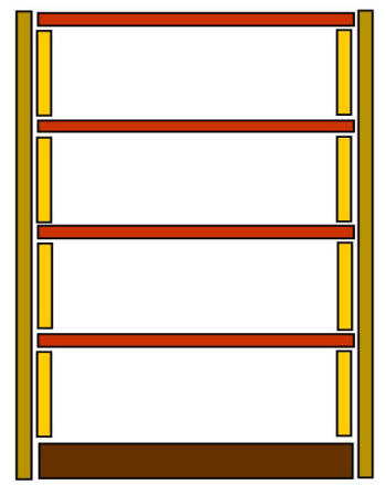
I don't explain here how the bookcase remains erect and how it supports the
loads - the books and any other items stored on the shelves, but one of the
factors making for stability is the weight of the items exerting their
downward force.
PHD general storage furniture
In the bedroom:
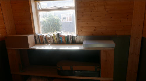
The vertical supports are sections of larch
sleeper.
The two shelves are of very different materials.
The lower shelf is far more substantial than it appears in the image - a
heavy slab of beech. The upper shelf is of plywood and very light. Any loads
placed on it will be very light. The storage furniture can easily be
dismantled. It took very little time to construct.
Below, view of far less of the structure - only the top shelf and some
items on the top shelf - and more of this part of the room.
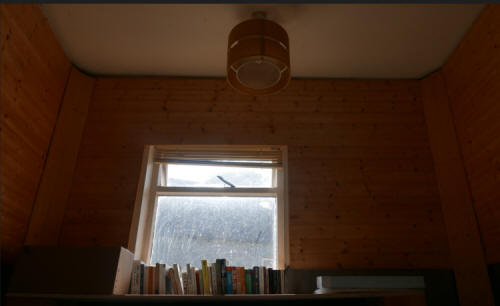
In the room which contains the new workbench:
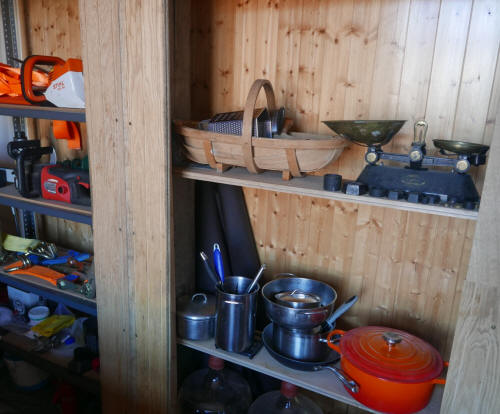
The vertical supports (only a little of the
support on the right) shown here, have oak cladding, worn in appearance. The
cladding conceals sections of oak sleeper which make up these very
substantial supports. As always so far, I haven't applied finishing of
varnish or another material. Finishing would improve the appearance of the
cladding. The design is quite radical, but I don't give any further
information here about the hidden features and my reasons for claiming that
the design is radical. The storage here is mainly for kitchen equipment.
Below the lower shelf are glass demi-johns and other bottles for storing
liquids. Apart from the workshop and general storage facilities, this room
is used as a kitchen. The kitchen downstairs was converted into a workshop
and cooking wouldn't be possible there. To the left of the wider vertical
support is a conventional storage structure constructed from Dexion
components. This is used to store some gardening and other equipment,
including a hedge trimmer, grass cutter and chain saw, some heavy duty
ratchet equipment and some brewing equipment and chemicals.
Also in the room which contains the new workbench:
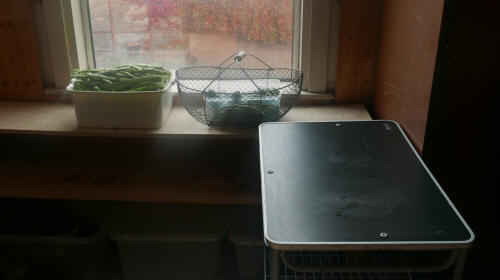
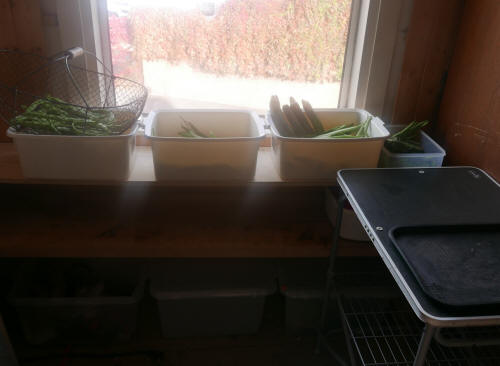
As with the storage furniture in the bedroom, this makes use of sections of
larch sleeper, with the addition of oak. The two shelves are of the same
materials as the bedroom storage sleeper, heavy beech and lighweight
plywood. I make use of another, bought, support for storage containers and
another one for food preparation. I could have used the workbench for food
preparation but as liquids are involved, it wouldn't be a good use of
the bench. The vegetables and fruit are from the allotments.
Graphic Design in wood
The letters making up 'FEFE' in this heading, from my pages on 'FEFE'

can be given many other typographical forms, including ones which can be
used not only in paper or Web media but given material form in many cases,
of course. This version could easily be constructed with wood and other
materials (the larger capital letters):

Other examples of 'logo' design which can easily be created in wood and
other materials:


Other examples of graphic design:


linkage

{theme}